MOBO4.3 HomePage Introduction
General
General
The Motherboard, or Mobo v4.3.4 BETA, is an addon board to plug onto the Softrock v6.3 RxTx, to transform it into an all band (160-10m) HF transceiver electronically controlled via USB.
Mobo v4.3.4 BETA is developed by a team of radio amateurs. The "core" members are Alex Lee (9V1AL), Mike Collins (KF4BQ), Loftur Jonasson (TF3LJ), Marc Olanie (F6ITU), and Art Allen (KY1K), with valuable contributions from many others.
Mobo External Connections
You can view photos of the Mobo v4.3.3 ALPHA in the Softrock40 Yahoo Group reflector, PHOTOS->9V1AL
Six (6) male headers (or rather footers) from the Mobo plug onto corresponding 6 receptacles on the SR v6.3:
- (footer P19) J1 and (footer P15) J2 - thus replacing the PAF modules. With the Mobo, there is no need to use any of the PAF modules. J2 will also provide the power supply to the Mobo.
- (footer P17) J3 and (footer K4) J4 - thus replacing the Rx filter modules. With the Mobo, there is no need to use any of the Rx filter modules.
- (footer P30) SW1 - the 2nd row of headers underneath the DIP switch. Do not install the DIP switch SW1 and install a 4-pin female receptacle on the 2nd row. This will provide the signal path for the Mobo to control the Si570 on the SR v6.3.
- (footer P32) PTT_I and Gnd - install a 2-pin female receptacle on the SR v6.3 and the Mobo will provide the Rx/Tx or PTT switching signal for the SR v6.3.
For further details on preparation of your Softrock, see the subsection "Prepare SR RXTX Board" in the Analog Power Busses documentation.
With the Mobo, the only external connections required will be:
- ANT connection to the SR v6.3
- +13.8V power supply to the SR v6.3
- I/Q input and I/Q output to the SR v6.3
- USB connector to the Mobo
A Note on the RXTX V6.3
A correctly functioning RXTX V6.3 is essential to success with the Mobo 4.3. You will be plugging the Mobo into and out of the RXTX several times during the project. When trouble-shooting, one wants to be able to rely (at least initially) on a proven assumption that the problem does NOT lie with the RXTX!
From Robert NQ0T: "Make sure your RXTXv6.3 is working properly. The MOBO didn't work for me when I first threw the switch. In the midst of inserting and removing the MOBO over and over again, things came loose on the 6.3 that I had thought were fine. On several occasions, I had to pull off the MOBO, put on the PAF, and BPF's and verify that the 6.3 was doing what it was supposed to. Having a functional 6.3, I found, helped immensely in getting the MOBO to run."
Features
The Mobo v4.3.4 BETA is a high performance upgrade to the Mobo v3.6. Some of the key features are:
- 8 band segments (instead of only 4 in Mobo v3.6)
- Use of up to 8 onboard filters multiplexed for both Rx and Tx and electronically switched. Each filter is on a plugin minifilter board, with flexibility of filter topology and characteristics. Two different sets of minifilters are offered in the BETA:
- SET A - 6 minifilters cover the whole 160-10m spectrum. Each filter is configured as a BPF with 3 SMT inductors and series and shunt SMT capacitors.
- SET B - 10 minifilters provide narrow bandwidth coverage from 160-10m. Each filter is configured as a BPF with 3 inductors and series and shunt SMT capacitors. For the lower freq bands, 160-40m, the builder can choose to use SMT inductors or toroids. Higher freq bands use toroidal inductors.
- Excellent 2nd (-40dB) and 3rd (-70dB) harmonics rejection can be achieved.
- Isolation of PC/USB from Softrock. There are separate digital and analog ground planes that are not galvanically connected. All control signals from the PC->USB->i2c on the digital side are isolated galvanically from the analog and SR side with the ADuM1251 chip. This reduces the RF noise from the PC/USB/uController from reaching the sensitive Rx circuitry, resulting in almost complete elimination of PC/USB caused spurious signals during Rx.
- Class A PA based on Mitsubishi RF MOSFET RD16HHF1
When biased to Class A (the biasing is done via software control and user customisable), a very linear output for SSB and digital modes is possible. When driven hard (beyond CLASS A limits), the linearity will decline. Measured IMD Ratios (a measure of the whole Tx chain's linearity) on the ALPHA build are:
- 1WPEP 48dBIMDR(tone to IMD level)
- 2WPEP 46dBIMDR
- 4WPEP 37dBIMDR
- 5WPEP 31dBIMDR
- 6WPEP 27dBIMDR
- 7WPEP 23dBIMDR
- Onboard uController running firmware compatible with Fred's v15.12 firmware for SR V.9 Rx
The USB uController, AT90USB162 is onboard the Mobo. Thus there is no need to use another controller eg. the USB-I2C Interface. The uController controls all aspects of the Mobo BETA operations and many parameters can be set up and changed with the PC based tool CFGSR.exe by Fred.
The
firmware developed by Loftur has greatly expanded capabilities, including:
- Control of the Si570 Programmable Crystal Oscillator, including "smoothtune" for seamless tuning between small frequency steps (<3500ppm)
- VFO, using a Rotary Encoder, and 9 short/long term memories, using a push button (cycle with short pushes, store with long)
- CW Paddle inputs
- PTT output
- PTT2 output (connected to SWR protect function)
- Automatic selection between 8 Bandpass filters, with user selectable switch points
- Automatic selection between 16 Lowpass filters, with user selectable selectable switchpoints, controls 2x PCF8574 8 bit GPIO extenders. Alternately or in parallel, it can also provide direct control of a 4 bit directly connected GPIO port.
- Measurement of Input voltage, PA current, Power forward and Power reflected (uses external Power/SWR bridge)
- Hi-SWR protect function, when using an external Power/SWR bridge (automatically lower PA bias and assert an external signal)
- PEP indication for power output (highest out of last 10 measured values)
- PA Temperature measurement and automatic Transmit Disable on a high temperature condition
- Manual PA Bias setpoint control, switching between different bias setpoints (such as between classes A and AB), and automatic calibration of the PA bias current
- 16x2 LCD display for Frequency readout, Power/SWR metering and status display (RX/TX/hi-SWR/hi-TMP/Mem-store...)
- 16x2 and 20x2 LCD display alternatives with analog-style bargraphs for power output and SWR visualisation
- 20x4 LCD and 40x2 display alternatives with analog-style bargraphs for power output and SWR visualisation Please see the following website for details: http://sites.google.com/site/lofturj/mobo4_3
- Power Ouput/ SWR measurement and SWR protection. With the optional PO/SWR Meter kit, the PO and SWR information can be displayed on the (optional) LCD display during Tx. When a high SWR condition is encountered, the Mobo PA is automatically biased to a low level of output for protection. The low level of output during protection will be useful for tuning antenna tuners.
- Provision for attaching many optional modules
The Mobo has been designed to allow modular, incremental addition of modules to enhance its functionality and capabilites.
Optional items (not supplied, not included in the BETA) include LCD display (industry standard char LCD displays, 16x2, 20x2, 20x4 or 40x2 supported) with backlight, rotary encoder and PO/SWR meter (kit can be ordered). These functions are already supported by the firmware.
Other optional modules are under development:
- electronically switched LPF (8 expandable to 16 bands) and Preamp/Step Attenuator board.
- SDR-Widget project. This will add a 192khz 24bit "sound card" capability to the Mobo, allowing a single HIGH speed USB connection to the PC for both rig control and I/Q signals.
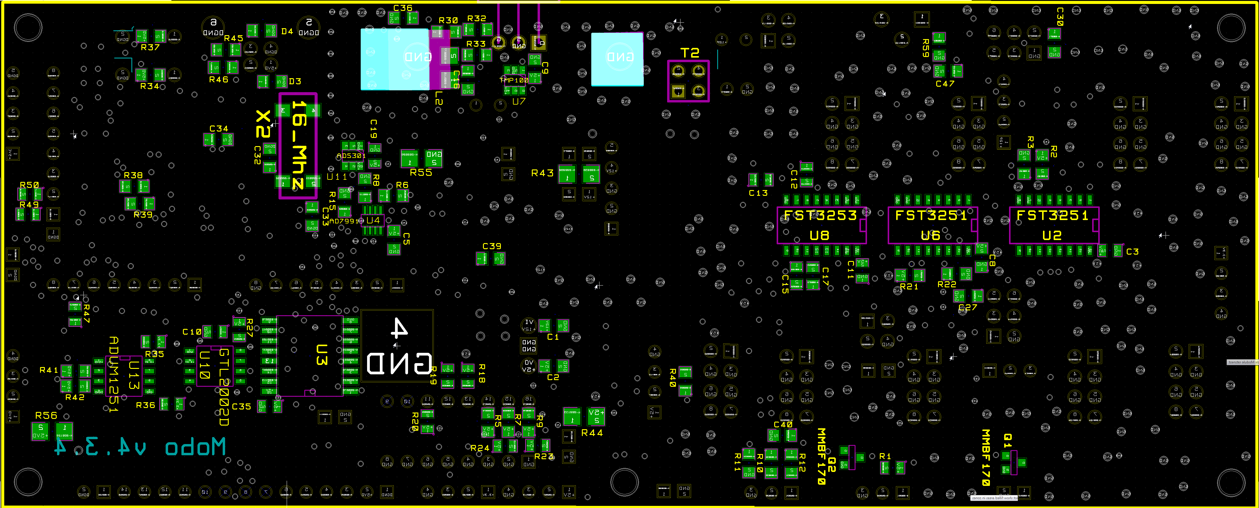
Theory of Operation
Click here to view the MOBO 4.3 main PCB's schematic diagram).
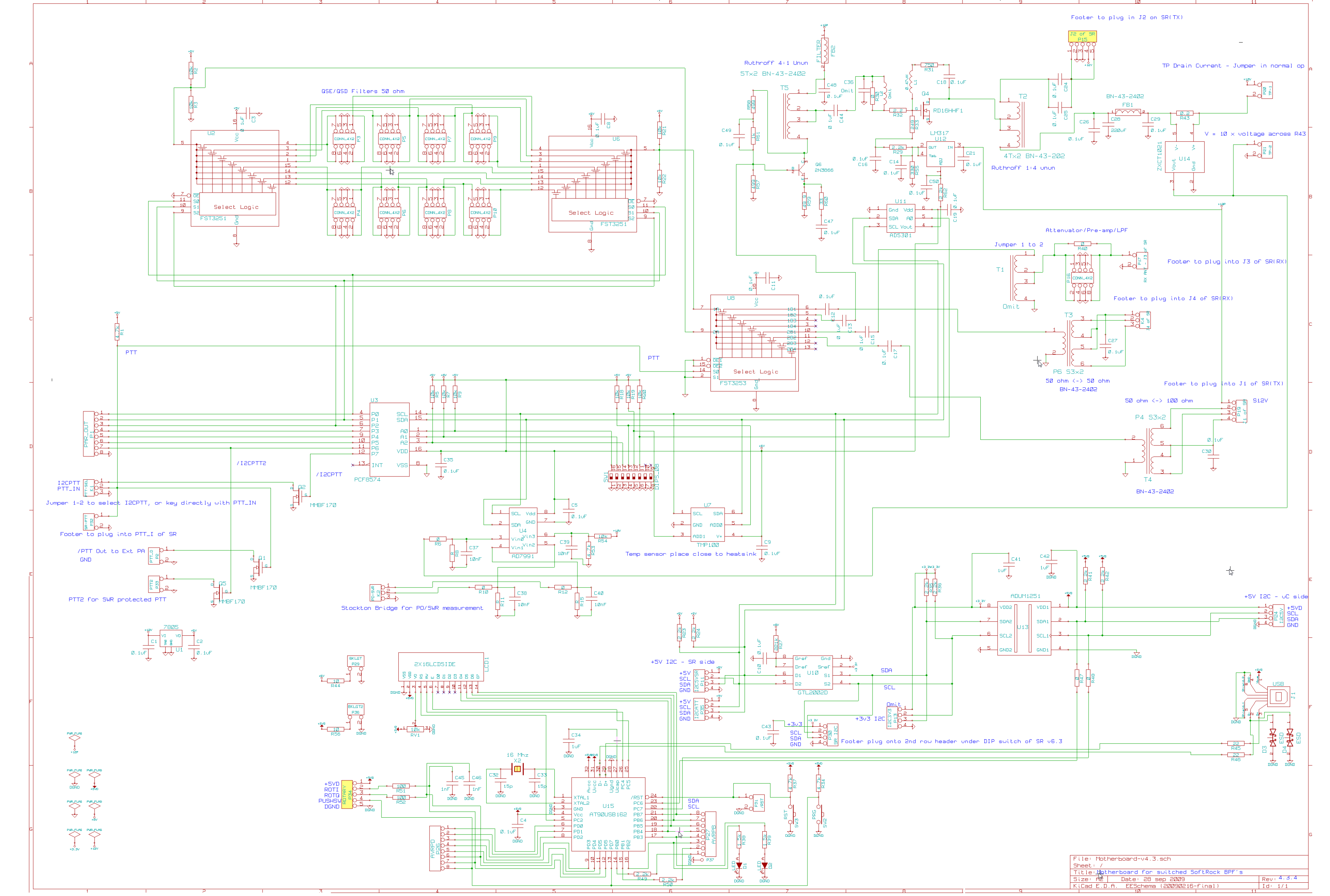
Click here for a hi-resolution view of the PCB top and bottom
(go directly to build notes) (go directly to build notes)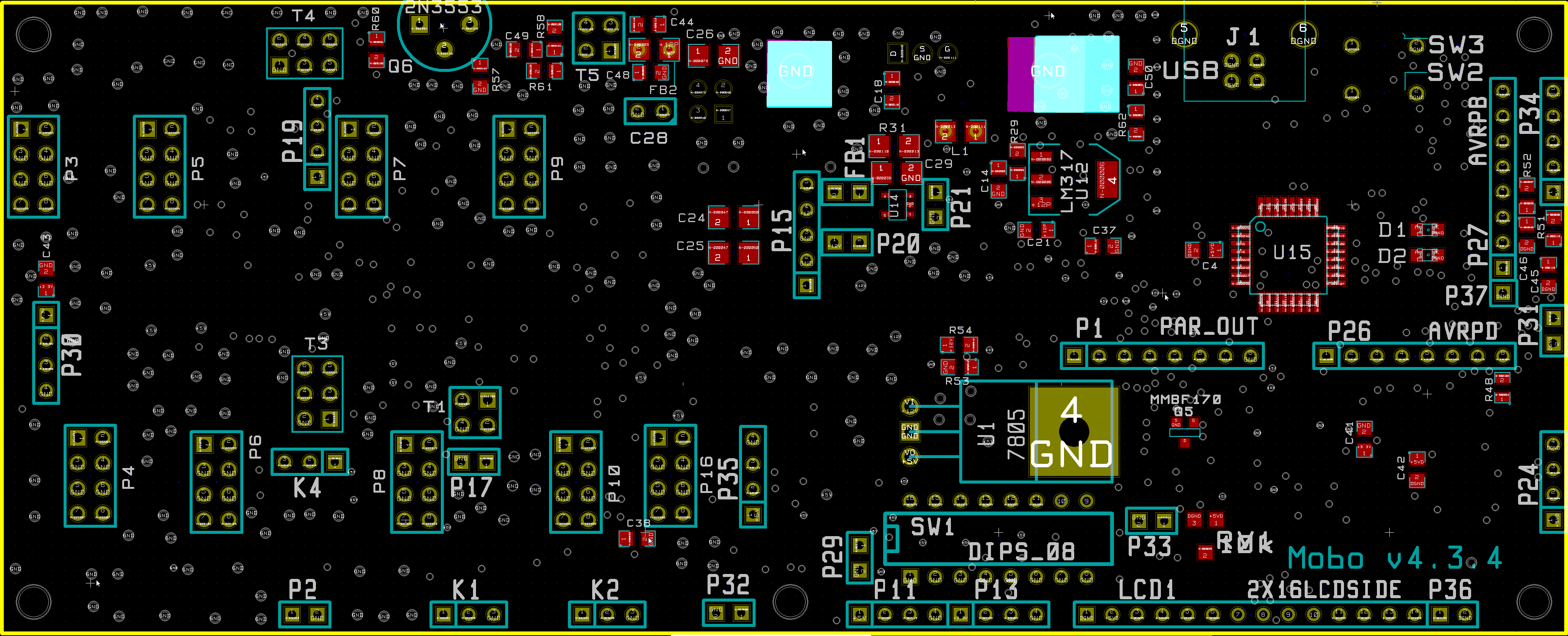
MOBO4.3 HomePage Bill of Materials
See Project Bill of MaterialsMOBO4.3 HomePage Expert's (terse) Build Notes
See Alex's notes on the Google Site. You must be an invited member of the Google MOBOKITS Group to view these notes.
Project Detailed Build Notes
For the non-expert builders among us, this site takes you through a stage-by-stage build of the kit. Each stage is self-contained and outlines the steps to build and test the stage. This ensures that you will have a much better chance of success once you reach the last step, since you will have successfully built and tested each preceding stage before moving on to the next stage.
Each stage is listed below, in build order, and you can link to it by clicking on its name below (or in the header and/or footer of each web page).
- Inventory the Bill of Materials
- Build and Test the Preparatory Steps Stage
- Build and Test the USB_Power Supply Stage
- Build and Test the Microprocessor Control Stage
- Build and Test the Analog Power Busses Stage
- Build and Test the I2C Bus Stage
- Build and Test the BPF Selector Stage
- Build and Test the Minifilters - A Stage
- Build and Test the Temp Sense/Bias Ctrl Stage
- Build and Test the Quadrature Sampling I/O Stage
- Build and Test the Transmitter PA Stage
- Build and Test the Power/SWR Control Stage
Background Info
Tools
Winding Inductors
To learn how to wind coils and transformers, please read the
- tips from the experts and then
- view the excellent videos on KC0WOXs Website
- or take a read of Dinesh's VU2FD guidelines.
- You can review the common construction techniques for inductors for details on deciphering the winding specifications, core specifications,and construction of toroidal and binocular inductors.
Soldering
If you are not experienced at soldering (and even if you are somewhat experienced at soldering), refer to Tom N0SS's excellent tutorial on basic soldering techniques.
The video below describes techniques for soldering SOIC 14 (and 16 and 8) SMDs
View the above in full-screen mode on Youtube.
For the more adventurous, there is a process using solder paste and an electric oven called the reflow process, which can be used to install all the SMT chips to one side of the PC Board. This is documented by Guenael Jouchet in the following Youtube segment:
- Read the Primer on SMT Soldering at the Sparkfun site. It is a very good read and it speaks great truths. Then take the time to watch the video tutorial on soldering an SOIC SMD IC.
- Solder Stations. Don't skimp here. Soldering deficiencies account for 80 percent of the
problems surfaced in troubleshooting. It is preferable to have an ESD-safe station, with a
grounded tip. A couple of good stations that are relatively inexpensive are:
-
 Velleman VTSS5U 50W Solder Station (approx $20 at Frys) (See BGMicro for Spare Tips)
 -
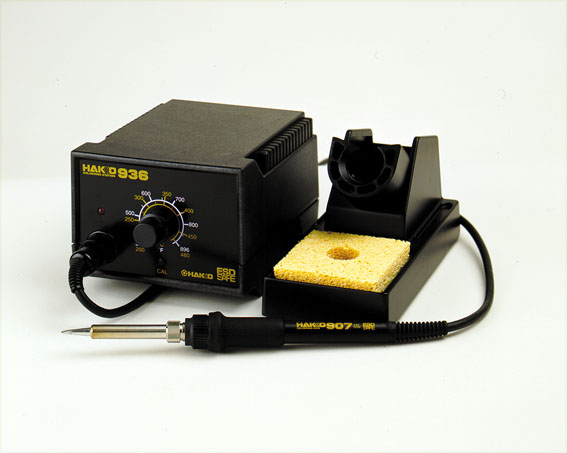 Haakko 936 ESD Solder Station (under $100)
-
ESD Protection
You may wish to review the message topic beginning at Message 43554 for a common-sense discussion on ESD.
- Avoid carpets in cool, dry areas.
- Leave PC cards and memory modules in their anti-static packaging until ready to be installed.
- Dissipate static electricity before handling any system components (PC cards, memory modules) by touching a grounded metal object, such as the system unit unpainted metal chassis.
- If possible, use antistatic devices, such as wrist straps and antistatic mats (see Radio Shack's Set for $25 or the JameCo AntiStatic mat for $15)).
- Always hold a PC card or memory module by its edges. Avoid touching the contacts and components on the memory module.
- Before removing chips from insulator, put on the wrist strap connected to the ESD mat. All work with CMOS chips should be done with the wrist strap on.
- As an added precaution before first touching a chip, you should touch a finger to a grounded metal surface.
- If using a DMM, its outside should be in contact with the ground of the ESD mat, and both leads shorted to this ground before use.
- See the review of ESD Precautions at this link.
Work Area
- You will need a well-lit work area and a minimum of 3X magnification (the author uses a cheap magnifying fluorescent light with a 3X lens. This is supplemented by a hand-held 10 X loupe - with light - for close-in inspection of solder joints and SMT installation.
- You should use a cookie sheet or baking pan (with four sides raised approximately a half an inch) for your actual work space. It is highly recommended for building on top of in order to catch stray parts, especially the tiny SMT chips which, once they are launched by an errant tweezer squeeze, are nigh on impossible to find if they are not caught on the cookie sheet.
Misc Tools
- It is most important to solidly clamp the PCB in a holder when soldering. A "third-hand" (e.g., Panavise or the Hendricks kits PCB Vise) can hold your board while soldering. In a pinch, you can get by with a simple third-hand, alligator clip vise. Jan G0BBL suggests "A very cheap way is to screw a Large Document Clip to a woodblock which will clamp the side of a PCB."
- Magnifying Head Strap
- Tweezers (bent tip is preferable).
- A toothpick and some beeswax - these can be used to pickup SMT devices and hold them steady while soldering.
- Diagonal side cutters.
- Small, rounded jaw needle-nose pliers.
- Set of jewelers' screwdrivers
- An Exacto knife.
- Fine-grit emery paper.
MOBO4.3 HomePage Completed Stage
Top of the Board
Bottom of the Board
MOBO4.3 HomePage Testing
Each stage will have a "Testing" Section, outlining one or more tests that, when successfully completed, provide you with the confidence and assurance that you are heading in the right direction towards a fully tested and built transceiver.
When you perform a test, you should always record the results of the test where indicated in the Testing section. This will make troubleshooting via the reflector much easier, since you will be communicating with the experts using a standard testing and measurement regime.
When comparing measurements to those published in these notes, the builder should be aware that actual and expected values could vary by as much as +/- 10%. The idea behind furnishing "expected/nominal" measurement values is to provide the builder with a good, "ballpark" number to determine whether or not the test has been successful. If the builder has concerns about his measurements, he should by all means pose those concerns as a query in the Softrock reflector so the experts can provide assistance.
This kit can be built and reliably tested using nothing more than a common multimeter. Tests assume that the builder has a decent digital multimeter of sufficiently high input impedance as to minimize circuit loading issues. Measurements will be taken of current draws, test point voltages, and resistances.
Most stages will have a current draw test, in which the builder tests the stage's current draw in two different ways:
- First, testing the draw through a current-limiting resistor
- Then, when that test is OK, removing the current-limiting resistor and measuring the real current draw.
The
IQGen or DQ-Gen
programs available free from Michael Keller, DL6IAK, can be used in
a pinch to get the sound card to produce audio tones for injection into the circuit.
You can always use Rocky to generate I and Q signals for tests requiring these audio signals (this is the author's preferred way)