Introduction
Theory of Operation
The mixer stage acts like two traditional direct conversion mixers operating in
tandem. Each takes in half of the filtered RF from the bandpass filter stage and
one of the quadrature center frequency signals, then "mixes" them, with an output
being the traditional mixer products, in this case, two audio frequency signals
that represent the difference between the two inputs (RF and Local Oscillator).
These two signals are referred to as the I (in-phase) and Q (Quadrature) signals
and are fed into the high gain Op-Amps stage for amplification and delivery to the
audio outputs (and, thence, to the PC's sound card). Resistors R11 and R12 form
a voltage divider to produce approximately 50 mV dc at pins 1 and 15 to enable the
mixer's operation when the /RXEN is grounded.
Schematic
This is a subset of the
overall schematic.
Note: red dot indicates resistor testpoints (hairpin, top, or left-hand lead)
Bill of Materials
| Designation | Value | Color/Code | Orientation | Category | Notes |
|---|
| U7 | FST3253 | | 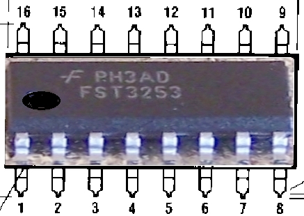 | SMT | |
| C22 | 0.01uF | | | SMT 1206 | |
| C23 | 0.01uF | | | SMT 1206 | |
| R11 | 10k |  | flat-v | | |
| R12 | 100 |  | flat-h | | |
| R13 | 10 |  | flat-h | | |
| R14 | 10 | | flat-h | | |
| Lead wire | | | | connector | Install a short, stout wire from a cut-off lead between the hole marked
/RXEN and the ground hole to its left |
Summary Build Notes
- Install SMT IC U7 (bottom)
- Install 2 SMT capacitors (bottom)
- Install 4 resistors
- Install ground strap for /RXEN
- Test the Stage
Detailed Build Notes
Bottom of the Board
Install U7
| Designation | Value | Color/Code | Orientation | Category | Notes |
|---|
| U7 | FST3253 | |
|
SMT SOIC-16 | |
Install SMT Capacitors
Watch out for solder splash when soldering C22 -
the pads are very close to the holes for R11's leads!
You might want to insert R11's leads into their holes prior to installing C22.
| Designation | Value | Color/Code | Orientation | Category | Notes |
|---|
| C22 | 0.01uF | | | SMT 1206 | |
| C23 | 0.01uF | | | SMT 1206 | |
Top of the Board
Install Resistors
| Designation | Value | Color/Code | Orientation | Category | Notes |
|---|
| R11 | 10k | | flat-v | | |
| R12 | 100 | | flat-h | | |
| R13 | 10 | | flat-h | | |
| R14 | 10 | | flat-h | | |
Install ground strap for RX Enable

| Designation | Value | Color/Code | Orientation | Category | Notes |
|---|
| Lead wire | | | | connector | Install a short, stout wire from a cut-off lead between the hole marked
/RXEN and the ground hole to its left |
Completed Stage
Topside
Bottomside
Testing
Note: Some tests in this stage require you to have built and plugged
in at least one bandpass filter.
If you have not yet done so, you can still conduct the current and voltage tests
provided you short pins 7, 8, and 9 of J1 together to provide the DC equivalent
of the T100 secondaries.
Current Draw(DMM)
- Current numbers here are for the CMOS version of the Si570. You will need
to adjust these up by about 14 mA for the LVDS version.
- Power the board up (author has been using an 11.6 Vdc battery pack
- Measure the current draw and 5 V rail voltage with a 1K Ω limiting resistor
- Measure the current draw without the limiting resistor.
| Testpoint | Nominal Value | Author's | Yours |
|---|
| Current Limited mA | 6-10 mA | 7.5 mA | ______ |
| Current limited 5V rail | 1-2 Vdc | 971 mV | ______ |
| Non limited draw mA | 90-100 mA | 97.4 mA | ______ |
Pin Voltages (DMM)
Measure U7 Pin Voltages
- Using a DMM, measure the dc voltage (with respect to ground) of the pins of U7.
- It is best to test for these voltages at the actual pins (not the pads), thereby
ensuring correct soldering of the pins to the pads.
| Testpoint | Nominal Value | Author's | Yours |
|---|
| U7, Pin 16 | 5 Vdc | 4.97 Vdc | ______ |
| U7, Pin 8 | 0 Vdc | 0 Vdc | ______ |
| U7, Pins 1and 15 | 50 mVdc | 49 mVdc | ______ |
| U7, Pin 2 | 2.5 Vdc | 2.48 Vdc | ______ |
| U7, Pin 14 | 2.5 Vdc | 2.48 Vdc | ______ |
| U7, Pin 7 | 2.5 Vdc | 2.48 Vdc | ______ |
| U7, Pin 9 | 2.5 Vdc | 2.48 Vdc | ______ |
If the voltage at pins 1 and 15 is not in the area of 50 mV, then the mixer will
not be enabled and there will be no outputs at pins 7 and 9.
If you see a high (~5 Vdc) voltage at pins 1 and 15,
check your /ENRX to be sure it is grounded