Schematic
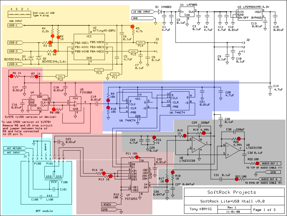
Below is the main schematic of the Lite + USB Xtall V9.0 SDR. The schematic has been partitioned into separate stages, each of which is covered in a separate page of build instructions in this web site. You can click on each shaded area and view the corresponding stage builders' notes.

Theory of Operation
- This receiver is patterned on the classic "direct conversion" receiver, in that it mixes incoming RF down to audio frequencies by beating the RF against a Local oscillator such that the mixer products are in the audio frequency range.
- Unlike the traditional DC receiver, the SDR does not "tune" the local oscillator's frequency to beat up against a desired RF signal. Instead, the local oscillator generates a fixed, "center frequency. The beauty of an SDR design is that the operator can, in one display, "see" all activity within the design bandwidth and immediately "click" on any interesting signal within that spectrum.
- This version (9.0) of the Softrock SDR receiver has a programmable local
oscillator (U4 in the schematic below), permitting the operator to select any
desired center frequency. Frequency selection is done in a SDR program on
the PC, and implemented via a USB connection and control circuit (U2 in the
schematic below). The local oscillator is the Silabs Si570, of which there
are two versions:
- LVDS - which requires U5, a high-speed, differential receiver that translates LVDS levels, with a typical differential input threshold of 100 mV, to LVTTL signal levels
- CMOS - which does not require the translation by U5
- While it would be tempting to use that frequency progammability to directly tune the oscillator to a specific desired frequency, the SDR design for Version 9.0 follows the SDR paradigm of providing a "chunk" of spectrum that is simultaneously detected and presented for processing in the PC. To accomplish this, the SDR hardware must present the "chunk" of spectrum as two down-converted chunks of AF in quadrature, the "I (in-phase) and the "Q" (quadrature) outputs.
- Most SDR designs use the concept of a center frequency, on either side of which are arrayed the "chunk" of received frequencies in a "chunk" of the RF spectrum. For any desired center frequency, the oscilllator (U4 - red shaded area below) generates a frequency equal to 4 times the desired center frequency. This signal is fed to a divider chain (U6 - blue shaded area below) that divides the input by 4 (with attendant phase shifts to achieve quadrature). The divider chain then outputs two signals at the desired center frequency and one-fourth of the input frequency. These two center frequency signals are in quadrature - each identical, differing only in phase by 90 degrees.
- The two center frequency signals are passed to the mixer stage (U7 - green
shaded area below), where they are mixed with and beat against the RF input from
the band pass filter stage (BPF Module, blue-green shaded area below), resulting in
two down-converted products that are quadrature AF analogues of the incoming RF
signals.
As a result, the mixer products can vary in audio frequency from
zero to +/- some theoretically high audio frequency.
(Note: the pluggable bandpass filters may be replaced by the new switchable HF BPF board , which implements 4 switchable BPFs on a single board, which can be manually switched or (once firmware is updated) switched via USB control.) - These AF signals are then amplified in an inverting operational amplifier (U8 - grey shaded area below) to produce the I and Q signals for consumption and digitization by the PC's sound card.
- The practical bandwidth achievable by this design is limited by the band pass filters and is one-half the soundcard's maximum sampling rate.
- The "tuning" , image rejection, demodulation, AFC and other neat radio functions happen in the software part of the Software Defined Radio. It is the magic of Software that makes for the extraordinarily high selectivity in the direct conversion hardware (which is notorious for great sensitivity but terrible selectivity). The software allows the display of the audio frequency manifestations of the RF "chunk" on a display calibrated in the RF domain and centered on the center frequency. It "pivots" the digitized I and Q audio signals around the center frequency, such that the signals that (in RF) were below the center frequency are displayed to the left of the center frequency and those that were (in RF) above the center frequency are displayed to the right of the center frequency. Since these mixer products are difference products, the single drawback of the SDR design is that any signals that are precisely ON the center frequency are inaccessible without changing the center frequency.