Power Supply Introduction
General
This phase provides the power bus for the G3020, via the (temporary) 12V feed and the regulated 5volt output for the Integrated Circuits.
It provides the 5 Volt power rail for the CMOS ICs (as well as provide for Power and TX LEDs and ttemporary 12 Volt input point). Make sure your external power supply has the correct volatge (12-13.8 Vdc) and it should be capable of producing 2 to 3 Amps. A faulty or underrated power supply is a very common problem.
(go directly to build notes)Power Supply Schematic
(go directly to build notes)
Power Supply Bill of Materials
Stage Bill of Materials
(resistor images and color codes courtesy of WIlfried, DL5SWB's R-Color Code program)
| Check | Count | Component | Marking | Category |
|---|---|---|---|---|
| ❏ | 1 | 1 k 1/4W 1% | br-blk-blk-br-br
 | 1/4W |
| ❏ | 2 | 2k2 1/4W 1% (2.2K) | red-red-blk-brn-brn
 | 1/4W |
| ❏ | 1 | 20 2W 5% | red-blk-blk-gld
 | 2W |
| ❏ | 1 | 1N4148 | 1N4148
 | Axial |
| ❏ | 5 | 100 nF | 104
 | Ceramic |
| ❏ | 1 | 47 uH molded inductor 10% | yel-vio-blk-slv
 | Choke |
| ❏ | 1 | shunt wire (cut-off lead) | Cutoff | |
| ❏ | 2 | 100 uF/25Vdc |
 | Electrolytic |
| ❏ | 1 | G3020 Printed Circuit Board | G3020 | |
| ❏ | 1 | misc hookup wire | Hookup | |
| ❏ | 1 | green LED |
 | LED |
| ❏ | 1 | red LED |
 | LED |
| ❏ | 1 | 78L05 voltage regulator | 78L05
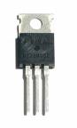 | TO-220 |
Power Supply Summary Build Notes
- Install Diodes
- Install Resistors and Capacitors
- Install Voltage Regulator and Electrolytics
- Install Choke, and Jumper
- Install Temporary Power Leads
- Inspect the Completed Stage
- Test the Stage
Power Supply Detailed Build Notes
Top of the Board
Install Diodes
Take care orienting the LEDs (the flat side of both LEDs is to the board's Outside edge).
Be sure to mount the 1N4148 signal diode with the band facing in the direction of the voltage regulator, as indicated on the silkscreen.
.| Check | Designation | Component | Marking | Category | Orientation | Notes |
|---|---|---|---|---|---|---|
| ❏ | D1-1 | 1N4148 | 1N4148
| Axial | ||
| ❏ | D1-2 | green LED |
| LED | ||
| ❏ | D1-3 | red LED |
| LED |
Install Resistors and Capacitors
| Check | Designation | Component | Marking | Category | Orientation | Notes |
|---|---|---|---|---|---|---|
| ❏ | C1-1 | 100 nF | 104
| Ceramic | ||
| ❏ | C1-2 | 100 nF | 104
| Ceramic | ||
| ❏ | C1-3 | 100 nF | 104
| Ceramic | ||
| ❏ | C1-4 | 100 nF | 104
| Ceramic | ||
| ❏ | C1-5 | 100 nF | 104
| Ceramic | ||
| ❏ | R1-4 | 20 2W 5% | red-blk-blk-gld
| 2W | ||
| ❏ | R1-1 | 1 k 1/4W 1% | br-blk-blk-br-br
| 1/4W | ||
| ❏ | R1-2 | 2k2 1/4W 1% (2.2K) | red-red-blk-brn-brn
| 1/4W | ||
| ❏ | R1-3 | 2k2 1/4W 1% (2.2K) | red-red-blk-brn-brn
| 1/4W |
Install Voltage Regulator and Electrolytics
Take care to orient the electrolytic capacitors so that their "+" lead (normally the longer lead) goes into the hole marked "+". The negative lead is normally the shorter lead and there is usually a grey band down the side of the capacitor to designate this negative lead. Failure to orient the electrolytic capacitors so as to respect proper polarization can lead to an unanticipated fireworks display!
The LM7805 5 Vdc voltage regulator must be installed such that the flat tab at the backside of the regulator can lay down to and be flush with the board per the silkscreen layout. This requires bending the leads to approximately a 90 degree angle and then fastening the tab (heatsink) to the board with a nut and bolt.
Careful: Don't make this mistake and install the regulator backwards:
| Check | Designation | Component | Marking | Category | Orientation | Notes |
|---|---|---|---|---|---|---|
| ❏ | U1-1 | 78L05 voltage regulator | 78L05
| TO-220 | Take ESD precautions | |
| ❏ | C1-6 | 100 uF/25Vdc |
| Electrolytic | ||
| ❏ | C1-7 | 100 uF/25Vdc |
| Electrolytic |
Install Choke, and Jumper
The 47 uH choke resembles a resistor but is a little shorter. There are 7 of these 47 uH (micro) in the kit, plus one 470 nH (nano).
| Check | Designation | Component | Marking | Category | Orientation | Notes |
|---|---|---|---|---|---|---|
| ❏ | JMP1-1 | shunt wire (cut-off lead) | Cutoff | |||
| ❏ | L1-1 | 47 uH molded inductor 10% | yel-vio-blk-slv
| Choke |
Install Temporary Power Leads
Connect leads to the points shown above for 13.8 Vdc power supply.
| Check | Designation | Component | Marking | Category | Orientation | Notes |
|---|---|---|---|---|---|---|
| ❏ | PWR1-1 | misc hookup wire | Hookup |
Inspect the Completed Stage
Check to make certain the voltage regulator, the electrolytic capacitors, and the 1N4148 diode are oriented correctly.
Maske sure the jumper was installed in the space just below the voltage regulator.
Power Supply Testing
Voltage Test
Test Setup
Test the voltage regulator for +5 Vdc (start out using a 100 ohm current-limiting resistor in series with the positive power lead - just to make sure there are no shorts.)
Test Measurements
| Testpoint | Units | Nominal Value | Author's | Yours |
|---|---|---|---|---|
| The jumper just below the pins on the voltage regulator | Vdc | +5 | tbd | _______ |