Introduction
This stage adds the TX Mixer to the board and provides the modulation of the Dividers' output signals by the 4 I and Q signals from the OpAmps. The result is a double sideband RF waveform that will be coupled into the PA stage.Schematic
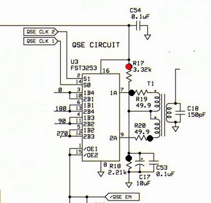
Bill of Materials
| Designation | Value | Orientation |
|---|---|---|
| C17 | 10uF/16 VDC Electrolytic | South-North |
| C18 | 150pF, ceramic, 5% | n/a |
| C53 | 0.1uF, smt 1206 | smt |
| R17 | 3.32 K, 1/4W, 1% | East-West |
| R18 | 2.21 K, 1/4W, 1% | West-East |
| R19 | 49.9, 1/4W, 1% | North-South |
| R20 | 49.9, 1/4W, 1% | West-East |
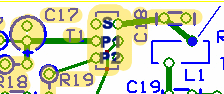
| T01 | T30-6 (yellow) (#30) (2.1 uH) | 24T/2x11T |
| U03 | FST3253 or SN74CBT3253D | SOIC 16 |
Build Notes
Testing
Current Draw
- With limiting resistor:
- Without limiting resistor, you should get ~38.5 mA
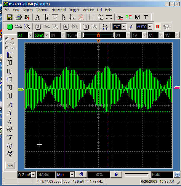
Mixer Output
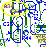
- Enable the chip. Connect the R39 hairpin hole to ground. Take care to get the correct hole (the right-hand, hairpin hole)
- Inject 16kHz audio signal into line in Left (or right). (Can use Rocky or IQGen to provide signals out of the computer's sound card)
- Connect scope probe to the top right pad of L1
- The trace should show a clean double sideband signal.
- Try the same for the other line out feed.