Introduction
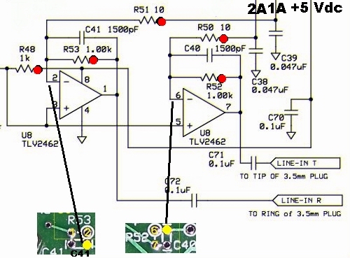
Schematic
Bill of Materials
| Designation | Value | Type | Orientation |
|---|---|---|---|
| C38 | 0.047uF, ceramic, 5% | n/a | |
| C39 | 0.047uF, ceramic, 5% | n/a | |
| C40 | 1500pF, ceramic, 5% | n/a | |
| C41 | 1500pF, ceramic, 5% | n/a | |
| C71 | 0.1uF, smt 1206 | smt | |
| C72 | 0.1uF, smt 1206 | smt | |
| Ctest1 | 5 uF dc blocking capacitor | n/a | |
| R48 | 1.00 K, 1/4 W, 1% | East-West | |
| R50 | 10.0, 1/4 W, 1% | West-East | |
| R51 | 10.0, 1/4 W, 1% | West-East | |
| R52 | 1.00 K, 1/4 W, 1% | North-South | |
| R53 | 1.00 K, 1/4 W, 1% | East-West | |
| U08 | TLV2462CD op-amp, SOIC 8 | SOIC 8 |
Build Notes
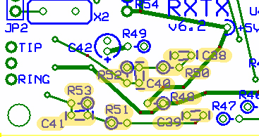
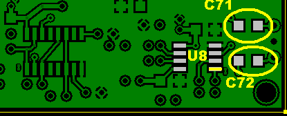
- Install U8. If your hands are the least bit shaky, be careful to protect the holes adjacent to pins 1, 3, 6, and 7 from solder splashover and consequent blockage. A fine point toothpick inserted into the hole will work.
- Install the SMT caps (C71, C72)
- Install the 4 ceramic caps (C38, C39, C40, C41)
- Install the 5 resistors (R48, R50, R51, R52, R53)
Testing
Current Draw
- After a successful current limiting resistor check on current draw, check the current draw of the circuit
- You should see a draw that is approximately 31 mA
Voltage Divider Test
- Measure the voltage at the hairpin of R49
- You should see the results of the voltage division of the 5 Vdc rail, approximately 2.5 Vdc
- If you do not get the expected result, check the soldering of R49 and R48
Op-Amp pin voltage tests
- In addition to using the convenient test points indicated in the table below, you should also double check by measuring the voltages on the actual IC pins (to detect the case of a poor or missing solder joint between the pin and the pad.
| Test Point | Expected Value | Units | Author Results | Measured Value |
|---|---|---|---|---|
| U8-1 (R53 hairpin) | 2.5 | vdc | 2.48 | |
| U8-2 | 2.5 | vdc | 2.48 | |
| U8-3 (R49 hairpin) | 2.5 | vdc | 2.48 | |
| U8-4 (GND) | 0 | vdc | 0 | |
| U8-5 (R49 hairpin – voltage divider) | 2.5 | vdc | 2.48 | |
| U8-6 | 2.5 | vdc | 2.48 | |
| U8-7(R52 hairpin) | 2.5 | vdc | 2.48 | |
| U8-8 (R48 hairpin) | 5 | vdc | 4.96 |
Op-Amp Test - no Scope
- Select a 2.21 k ohm resistor from the available parts
- measure the voltage at the hairpin of R53
- using clip leads, connect the hairpin of R51 in series with the 2.2k resistor to ground
- measure the voltage at R53
- it should be approximately 1.45 times the initial measurement
- repeat this same test on the second Op-Amp, substituting R50 and R52 for R51 and R53, respectively, to get the same results
- If this test fails, check the installation and soldering of U8 and the resistors.
Op-Amp Test - Scope
- Connect a signal generator set to 10-20khz at 10 mV amplitude through a ~5uF coupling capacitor to the above test points. The frequency isn't particularly critical as the receiver will output signals in the 1-100khz frequency range. The voltage isn't either as long as you don't get too large. I tested mine and it didn't flattop the output until a little over 4 volts pk-pk out. (Courtesy of Leonard KC0WOX)