Introduction
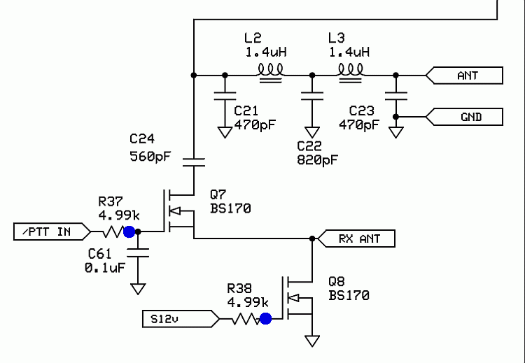
We're getting close to the end. This stage provides the complete paths from the antenna to the RX and TX functions. Q7, which we have been shunting for our RX tests, provides the switching of the Antenna terminals to the RX ANT stub.Schematic

Bill of Materials
| Designation | Value | Orientation |
|---|---|---|
| C21 | 330pF, ceramic, 5% | n/a |
| C22 | 680pF, ceramic, 5% | n/a |
| C23 | 330pF, ceramic, 5% | n/a |
| L02 | T37-6 (yellow) (#26) (0.77 uH) | 16T |
| L03 | T37-6 (yellow) (#26) (0.77 uH) | 16T |
| Q07 | BS170 FET | TO 92 |
| Q08 | BS170 FET | TO 92 |
| R37 | 4.99 K, 1/4W, 1% | North-South |
| R38 | 4.99 K, 1/4W, 1% | North-South |
Build Notes

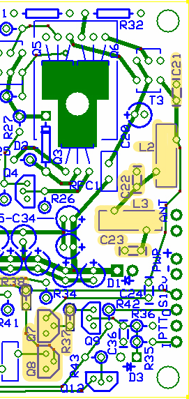
- Wind and install L2 and L3 (11" of #30 per coil)
- Install C21 and C23
- Install Q7 and Q8
- Install R37 and R38
Testing
Current Draw
Still should read about 38 mA
Continuity Tests
You should have continuity from ANT to the top hole of C24
RX Functioning
- Set up Rocky for receiving in the band of interest (e.g., center freq = 7.056 MHz)
- Connect the Line In pads to the PC sound card's stereo Line In or stereo mike inputs
- Set up your signal generator to generate RF at a frequency within 5 or 10 kHz of the center frequency. (Author used MFJ antenna analyzer set at 7.040 MHz.
- Couple the signal to the ANT input of the board
- Run Rocky
- Power up the board
- You should see the signal in Rocky's spectrum display at the frequency of the generator.
- If your RF source can sweep the frequency, do so and you should see the result as a "hump" traveling up or down the spectrum display as the frequency changes