Introduction
This stage adds the TX Mixer to the board and provides the modulation of the Dividers' output signals by the 4 I and Q signals from the OpAmps. The result is a double sideband RF waveform that will be coupled into the PA stage.
Theory of Operation
Let's suppose you were working 40m with a SDR center frequency of 7.056 MHz. You have tuned your SDR (via the software) so that you are listening to a CW station on 7.066 MHz (10 kHz up from the center frequency).
If you were to listen to the I and Q signals from the hardware RX via an amplifier or headphones (assuming there were no other signals and little noise) you would hear a single 10 kHz CW signal on both channels. Your ears may or may not be able to detect the fact that the tone in one ear is 90 degrees out of phase (I.e., In quadrature) with the tone in the other ear.
By comparing the phase difference between the I/Q signals the SDR RX software determines that this signal is 10KHz higher than the center frequency and displays the CW signal as a broken line on the waterfall. It also frequency shifts this signal at the output of the soundcard so it is heard at as normal CW tone from the speakers.
Now, assume you decide to transmit on that frequency where you have placed your cursor (7.066 MHz). Your SDR software will emit a 10 kHz signal (the delta between the center frequency and the selected TX frequency) in both the I and Q outputs, again, in quadrature. This will go into the SDR hardware on the TX side, through the OpAmps and into the mixer, where it will beat up against the LO center frequency of 7.056 MHz. The input to the mixer is 10KHz from the soundcard; the output from the mixer is the RF product of the LO and the input 10 kHz signal. If you were to listen to the input 10 kHz signal you would hear a tone. This tone is audible simply because it represents the delta between the center frequency and the desired transmit frequency, in this case, only 10 kHz, and, since it is in the range of audio frequencies, is audible. If you were to select a higher frequency on whch to transmit, sat 7.080 MHz, the resultant signal would be a 24 kHz signal; perhaps your dog would hear it, but you certainly would not!
The TX OpAmps are unity gain and serve to split the incoming I and Q signals into 4 components: 0, 180, 90, and 270 degree phase. Each of the four are then input to the Mixer and are switched ("mixed" by the LO signals which are 90 degrees apart in phase). The two outputs of the mixer are the up-converted RF products, in anti-phase (I.e., 180 degrees apart). These are fed to the PAF and its input transformer.
The PAF Input Transformer, T200, will cancel out one or the other of the anti-phased RF signals out, depending upon which is leading and which is lagging. This is just like the RX, any minor phase errors are compensated. The software will make the phase and level of the I/Q signals such that the mixing product 10KHz below 7.056 is cancelled leaving a signal 10KHz above 7.056 at the output of the PAF Input Transformer.
The SDR software sends two suitably phased signals from the soundcard it is not that tone that is transmitted, but an up-converted mixer RF product, amplified and filtered in the PAF board.
Schematic
(Click for full TX Schematic)
Summary Build Notes
- Install sockets J1 and J2
- Install Resistors R15 through R18
- Install electrolytic Cap C16
- Install U3
- Test the Stage
Bill of Materials
| Check | Designation | Component | (Color) Code | Type | Qty | Notes |
|---|---|---|---|---|---|---|
| [__] | C16 | 10 uF 16V | electrolytic | 1 | S=+ | |
| [__] | J1 | 4-pin socket | connector (female) | 1 | ||
| [__] | J2 | 5-pin socket | connector (female) | 1 | ||
| [__] | R15 | 3.32 k | orange-orange-red-brown-brown | Resistor 1% | 1 | FlatV |
| [__] | R16 | 2.21 k | red-red-brown-brown-brown | Resistor 1% | 1 | FlatV |
| [__] | R17 | 49.9 | yellow-white-white-gold-brown | Resistor 1% | 1 | FlatV |
| [__] | R18 | 49.9 | yellow-white-white-gold-brown | Resistor 1% | 1 | FlatV |
| [__] | U3 | FST3253 | SOIC-16 Dual 4:1 Mux/Demux Bus Switch | 1 | (bottom) |
Detailed Build Notes
Sockets
- From the PAF kit, take the PAF board and plugs P201 and P202
- Install the plugs to the bottom side of the PAF board with the short leads of each plug inserted into the holes and protruding from the bottom to the top and the long leads protuding from the bottom of the PAF board.
- Using the PAF board and its plugs as an alignment jig, plug it into the sockets J1 and J2
- Mount and install the sockets J1 and J2 onto the topside of the Main Board
- Remove the PAF board and set aside until later
Resistors and Capacitor
- Install Resistors R15-R18
Note they are all oriented flat, vertical. - Install electrolytic capacitor C16
Mixer SMT IC
Install The FST 3253 TX Mixer, U3Usual ESD and solder splashover precautions apply.
Completed Board
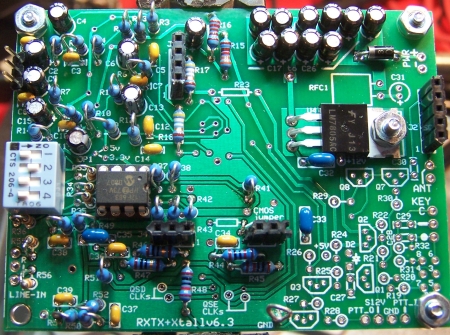
Topside
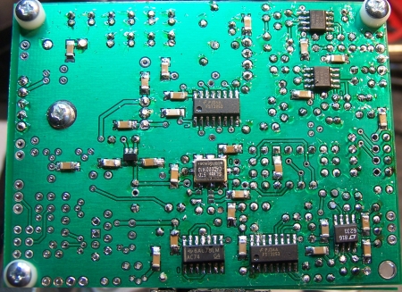
Bottomside
Testing
Current Limited Power Test
- Connect a 100 ohm resistor in series with the power line and apply 12 V dc power
- the current should be less than 120 mA (nominally 105 mA)
- Measure the voltage WRT ground at the +5 V and at the 3.3 Vdc testpoints.
- A voltage of around 2 V dc indicates the power rails are not shorted
- Remove the current-limiting resistor. Subsequent tests in this stage are with the current-limiting resistor OUT of the circuit.
Current Draw
- Without limiting resistor, you should get < 103 mA
- Your measurement: _____________________________
Mixer Pin Voltages
- Temporarily ground pin 1 of U3 by jumpering the hole for the hairpin lead of R26 to the ground lead.
- Jumper pins 2, 3, and 4 of jack J1 (this establishes the correct dc level for pins 7 and 9 of the mixer)
- Measure the voltages at the mixer pins as indicated below:
| Pin | Nominal Value | Author Results | Your Measurement |
|---|---|---|---|
| 1&15 (hole for R26 hairpin) | ~0 Vdc | ||
| 8 | 0 | ||
| 16 | 5 V rail | ||
| 2 & 14 (QSE CLK 1 & 2) | ½ 5V rail | ||
| 7(R18 hairpin) | around 2 volts | ||
| 9 (R17 hairpin) | around 2 volts | ||
| 3 (see picture above right) | around 2 volts | ||
| 4 (see picture above right) | around 2 volts | ||
| 5 (see picture above right) | around 2 volts | ||
| 6 (see picture above right) | around 2 volts |