Introduction
One of the more common problems in building a Softrock is the problem of image rejection.
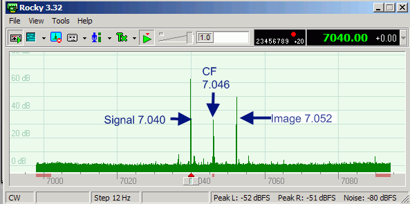
The problem is shown below. Given a Softrock with a center frequency of 7.046 MHz and an injected signal of 7.040 MHZ, an image rejection problem exists when the mirror image of the signal exists at 7.052 MHz (oposite side of the center frequency from the desired signal and displaced an equal amount therefrom):
Image Problem - Image not rejected

MUST Have Stereo Inputs to PC
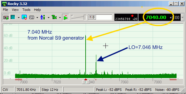
In order to reject unwanted images, the SDR software MUST have two discrete audio inputs - I (In-Phase) and Q (Quadrature) - that are equal in frequency and 90 degrees apart. These inputs make it possible to reject images, as shown below:
Image Rejected

Causes and Remedies
In nearly every instance, the problem can be attributed to one of the following causes:
Hardware:
failure of the board to produce two distinct I and Q signals, e.g.:- shorted leads
- bad solder joints around the RX OpAmp outputs
- failure to produce two distinct QSD signals from the dividers,
- bad or improper windings/soldering on phasing transformer in the bandpass filter stage.
Interconnections:
- Bad or shorted connection of cable to the Ring and Tip pads on the board
- Defective cable (inter wire shorts and/or cross-talk; continuity break)
- Line in/line out plugs are fully into their stereo sockets on the sound board. If they are a bit tight it is easy not to notice that they aren't fully engaged. (TX John G0UCP)
Sound Card:
Improper settings on the sound card (must be stereo input; many soundcards, unfortunately, have only a monaural microphone imput - these will not work for SDR.- Not stereo. If the sound card does not support stereo inputs, it cannot support SDR.
- IQ Output check the cable/plug with an ohmmeter to be sure there are three, clean (zero ohms), independent continuity paths (left, right, common)
- check the balance control to be sure it is centered between each channel
- check the volume control settings on the input
- Other settings.
- "What-you-hear" (also known in some cases as "Stereo Mix") must NOT be enabled
- In the Soundblaster Live 24, "Enable Monitoring" must not be on
Software:
Incorrect settings in Rocky (or the SDR software being used) - often the problem will be attributed to the wrong sample shift settings. If the above fixes do not eliminate the images, try the RX test using each of the three sample delay settings available in the View / Settings menu. You may need to quit Rocky after changing the settings and then restart and retest at the new setting.
Excerpts from the Reflector
- Tony KB9YIG:
- No RX image rejection results when one of the I / Q signals from the RXTX board is missing or not getting to stereo line-in inputs to the soundcard. If both signals are the same it will also result in no RX image rejection.
- The problem could be on the RXTX board, in the cable or at the soundcard.
- Also, if I and Q signal lines are shorted together no image rejection will be the result.
- If you have an 40m RF source with an output of 0.2 volts p-p and can observe the TIP and RING outputs relative to ground on the RXTX board, you should be able to see two sine waves of about 2 volts p-p that have a 90 degrees phase relationship to each other.
- There have been a few cases of (the RX Opamp IC) failing due to an AC potential between the soundcard ground and the RXTX circuit ground. (RxOpamp) pin 1 and pin 7 DC levels should be around 2.5 volts relative to circuit ground if (RX Opamp IC) is good.
- If (T100) is not wired correctly to the (BPF) board no RX image rejection can also result. Check for proper routing of the (T100) leads as shown in the BPF Stage or a problem with soldering of (T100) leads to the (BPF) board
- Tim AB0WR: Get into your audio mixer and see if you can change the input from being a "microphone" input to being a "line in" input. The actual input jack may be stereo but it may only be used as a stereo input when used as a "line in" input.
- Cecil K5NWA:
- No, you have one of the signals not getting to the PC, check your cabling, the two signals are used to cancel images if one of them is missing you have no image rejection.
- Make sure you are connected to a stereo input of the sound card not a mono microphone input.
- Check your SoftRock for wrong components, parts inserted in the wrong holes, solder shorts
- the transformer (on the BPF board) is an area where a lot of people make mistakes, did you scrape the wires before soldering?
- Pete M0FMT
Assuming that Rocky is correctly installed, that the sound card is a stereo soundc ard, the input to the soundcard is a STEREO input, and the cables and connectors are stereo cables with a good stereo connection. I.e. there are no whiskers connecting the two inputs together or a disconnected input for I or O, then the issue is with your new build. Suggestions are:-
- First of all check the input transformer connections are correct. The phasing of the input signals to the QSD chip is vital. These connections must be correct in order to provide the two RF signals in antiphase (0 and 180 degrees) to the QSD Mixer
- Check your output I/O. To do this:
- disconnect one output at a time at the Soft rock card and run your soft rock.
- If the image condition exists and signals are approx the same amplitude with either one of the outputs disconnected then you know the two op amps are working and need no attention. I.e. no soldering bridges or incorrect value components. This indicates the problem originates elsewhere.
- If there is a total loss of signal when one or other of the outputs are disconnected then your problem is in that part of the circuit. Check carefully all components are in place and no dry joints or bridges.
- Bridges are an issue around the pins of the SMT chips, a big help here is to use a solder wick and some free flux to remake these connections.
- Assuming all is well in the above checks, check the QSD mixer chip for solder bridges by using the method suggested above
- Similarly repeat this for the 74HC74 divider chip(s).