Introduction
This is the home page for the Detailed Builder's Notes for the Softrock RXTX V6.2 Software Defined Radio transceiver, from a series of SDR kits offered by Tony Parks KB9YIG. This has been a work in progress, as the author moved through an actual build. The build was of the 40/30m version of the kit. These instructions and included component values may vary somewhat when used with kits for other bands.Much of the documentation was initially developed entirely from the original documentation and based upon an excellent work by Leonard, KC0WOX, without which this could not have been accomplished. As the build progressed, the author posted necessary changes to the affected web pages. If your browser is caching pages, you may need to hit the "refresh" key (F5 on IE and Firefox) to get the latest version of the page.
The intent in providing these detailed instructions is to help the less experienced builder through what might otherwise be a daunting task. The instructions provide a stage-by-stage build process, allowing the builder to build a single stage and then test it ("sanity check") before moving on to the next stage.
Some stages may provide considerable background info. For those who would rather skip the background info and just get with the building, the critical steps and tests in each stage will be highlighted by special Icons:
This icon identifies a step in the build stage
This icon identifies a test operation in the build stage
The builder can register into the Softrock users group on Yahoo to pose any questions, comments, or issues to the many talented users/builders who are constantly posting to and reading from that group.
Any comments or corrections would be most appreciated and should be directed to the author, Robby WB5RVZ.
Credit is due to several sources, including, but not limited to, Tony KB9YIG, Leonard KC0WOX, and Alex VE3NEA.
Schematic
Each stage will begin with a subset of the overall schematic diagram. You can reference the two full diagrams provided with the kit by clicking on the following links:
Schematics have been annotated with "fat" dots on the "hairpin" end of resistors which are mounted as such. This provides the builder with come convenient test points (i.e., the "hairpin" leads) immediately recognizable in the schematics.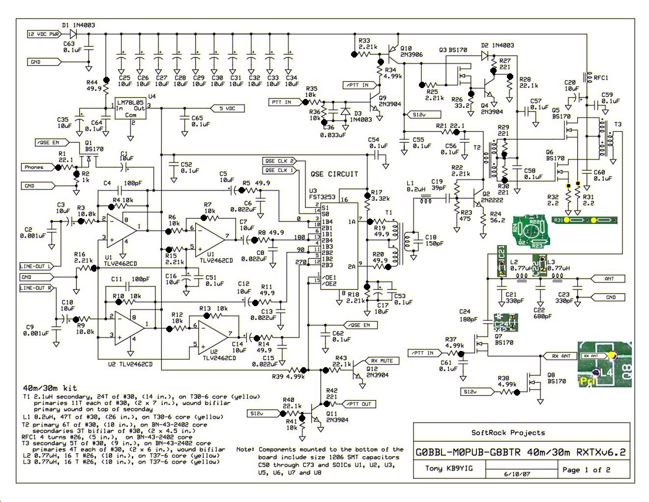
Bill of Materials
Before beginning work on the kit, you should inventory it against the Billof Materials. In each stage, there will be a subset of the Bill of Materials related to that stage alone. You can use that subset as a checklist of the components to be installed in the stage.
Build Notes
You can review Tony's original builder notes for a quick overview of the overall build. Please keep in mind that Tony's notes do not use the stage-by-stage approach used in these enhanced notes.
Each stage will have a set of graphics (board top and bottom) and instructions (where needed) on how to complete that stage. Obvious work is not specifically stated. However, where there may be "gotchas" or special techniques or special sequences of tasks, they will be noted under the "Build It" icon
- Inventory the Kit in the Bill of Materials (BOM)
- Power Supply
- Local Oscillator
- Dividers
- RX RF Input
- RX Opamps
- RX Mixer
- TX OpAmps
- TX Mixer (QSE)
- PTT
- RX Switching
- Phones
- Antenna Switching
- PA
Testing
Tests assume that the builder has a decent digital multimeter of sufficiently high input impedance as to minimize circuit loading issues. Measurements will be taken of current draws, test point voltages, and resistances.
When comparing measurements to those published in these notes, the builder should be aware that actual and expected values could vary by as much as +/- 10%. The idea behind furnishing "expected" measurement values is to provide the builder with a good, "ballpark" number to determine whether or not the test has been successful. If the builder has concerns about his measurements, he should by all means pose those concerns as a query in the Softrock reflector so the experts can provide assistance.
The audio generator need only be capable of generating a relatively low-level tone of a few kHz. The IQGen or DQ-Gen programs available free from Michael Keller, DL6IAK, can be used in a pinch to get the sound card to produce audio tones for injection into the circuit.
You can always use Rocky to generate I and Q signals for tests requiring these audio signals (this is the author's preferred way)
The RF generator should be capable of generating a few millivolts at one of the center frequencies of the receiver. The author has successfully used the multifunction HF TestSet from the Four States QRP Club. This kit includes a nice frequency counter, as well. Unfortunately, this fine little kit is sold out. However, the builder may want to peruse the schematic of the kit to get ideas for putting together AF and RF generating circuits.
Another excellent and inexpensive RF generator that can produce a clean 50 mV signal on four different bands is the Norcal S9 Signal Generator. It has the added bonus of being an excellent "starter kit" for those who have never done any SMT soldering.
Background Info
Tools
Soldering
Read the Primer on SMT Soldering at the Sparkfun site. It is a very good read and it speaks great truths. Then take the time to watch the video tutorial on soldering an SOIC SMD IC.
ESD Protection
- Avoid carpets in cool, dry areas.
- Leave PC cards and memory modules in their anti-static packaging until ready to be installed.
- Dissipate static electricity before handling any system components (PC cards, memory modules) by touching a grounded metal object, such as the system unit unpainted metal chassis.
- If possible, use antistatic devices, such as wrist straps and antistatic mats (see Radio Shack's Set for $25).
- Always hold a PC card or memory module by its edges. Avoid touching the contacts and components on the memory module.
- Before removing chips from insulator, put on the wrist strap connected to the ESD mat. All work with CMOS chips should be done with the wrist strap on.
- As an added precaution before first touching a chip, you should touch a finger to a grounded metal surface.
- If using a DMM, its outside should be in contact with the ground of the ESD mat, and both leads shorted to this ground before use.
- See the review of ESD Precautions at this link.
Misc Tools
- Magnifying Head Strap
- Tweezers (bent tip is preferable).
- Diagonal side cutters.
- A "third-hand" (e.g., Panavise or the Hendricks kits PCB Vise) to hold your board while soldering. In a pinch, you can get by with a simple third-hand, alligator clip vise.
- Small, rounded jaw needle-nose pliers.
- Set of jewelers' screwdrivers
- An Exacto knife.
- Fine-grit emery paper.