Power Supply Introduction
General
In this first (and following) stages, the builder should remember that one of the most common causes of errors is soldering. It pays to review materials on soldering, get help from Elmers, or whatever you can do to make your solder joints as clean and properly conductive as possible!
The second most common cause of errors is installation of the WRONG component and/or installing the component in the wrong ORIENTATION. The old rule of "measure twice, cut once" clearly applies to this project. Be especially careful and beware that it is very easy to install the wrong resistor depending entirely in color codes. While color codes are helpful in initially sorting resistors out, it is imperative that you validate that you have the correct resistor by double checking with your ohmmeter. While the ohmmeter reading will never be the exact value, for most of the resistors in this kit, the ohmmeter will get you to within 1% (a very few some are within 5%) of the stated value
The remaining one-tenth of one percent of the causes of errors is the defective component - most suspect the component immediately; the intelligent rarely look first at possible component failure.
Theory of Operation
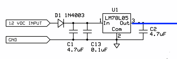
This stage provides the +5 volt power rail for the radio. The incoming voltage (from 9 - 12 Vdc) is regulated by U1 to a nominal 5 Vdc (4.5 - 5.1 Vdc range). D1 serves to protect the circuit from accidentally reversed polarity.
Power Supply Schematic
(Resistor testpoints (hairpin, top, or left-hand lead), as physically installed on the board, are marked in the schematic with red dots)
(Click for Full Schematic)
(above schematic has clickable areas that can be used for navigation)
(go directly to build notes)Power Supply Bill of Materials
Stage Bill of Materials
(resistor images and color codes courtesy of WIlfried, DL5SWB's R-Color Code program)
| Check | Count | Component | Marking | Category |
|---|---|---|---|---|
| ❏ | 1 | 1N4003 | 1N4003
 | Axial |
| ❏ | 2 | 4.7 uF 10% 16V X7R RAD | 475
 | Ceramic |
| ❏ | 1 | shunt wire (cut-off lead) | Cutoff | |
| ❏ | 1 | SR Lite II (Combined) PCB | Main Board | |
| ❏ | 1 | 0.1 uF | (smt) black stripe
 | SMT 1206 |
| ❏ | 1 | LM78L05 voltage regulator | LM78L05
 | TO-92 |
Power Supply Summary Build Notes
- Install SMT cap
- Install topside components
- Install ground test loop
- Test the Stage
Power Supply Detailed Build Notes
Bottom of the Board

Install SMT cap
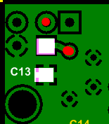
Install C13 SMT 0.1 uF cap
Take care to avoid solder "splashover" that could clog up the thru-holes above and to the right of C13 (see red dots in above graphic)
See hints on installing SMT Caps.| Check | Designation | Component | Marking | Category | Orientation | Notes |
|---|---|---|---|---|---|---|
| ❏ | PCB | SR Lite II (Combined) PCB | Main Board | |||
| ❏ | C13 | 0.1 uF | (smt) black stripe
 | SMT 1206 | SMT |
Top of the Board

Install topside components
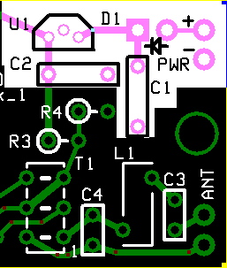
Install C1 and C2 (the two blue capacitors), U1, and D1. Install D1 such that the cathode end (the end with the band) is facing up and forms a hairpin. The hairpin lead will go into the square thru-hole (refer to the Completed Stage, Topside picture below).
See hints on identifying and installing Ceramic Capacitors
Take care to correctly identify the Voltage regulator, U1. It is a TO92 package, as are the 2N390x transistors. Some have had the misfortune of installing one of the 2N390x transistors in this stage, with strange results.
| Check | Designation | Component | Marking | Category | Orientation | Notes |
|---|---|---|---|---|---|---|
| ❏ | U1 | LM78L05 voltage regulator | LM78L05
 | TO-92 | Take ESD precautions | |
| ❏ | D1 | 1N4003 | 1N4003
 | Axial | E-W | |
| ❏ | C01 | 4.7 uF 10% 16V X7R RAD | 475
 | Ceramic | ||
| ❏ | C02 | 4.7 uF 10% 16V X7R RAD | 475
 | Ceramic |
Install ground test loop
Using a short length of cut-off resistor or capacitor lead, fashion a short wire loop and solder it to the "ground" hole, such that the loop is available on the topside to provide a ground point for tests.

| Check | Designation | Component | Marking | Category | Orientation | Notes |
|---|---|---|---|---|---|---|
| ❏ | gnd | shunt wire (cut-off lead) | Cutoff |
Power Supply Testing
Visual Inspection
Test Setup
Using very good lighting and magnification, carefully inspect the solder joints to identify bridges, cold joints, or poor contacts.
Current Draw
Test Setup
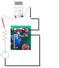
Test for current draw in 2 ways:
- Use a 12 volt power supply
- In one test there is also a 1k resistor in the series "chain" as well.
- in the second test, the setup is the same except that the current-limiting resistor is removed

Test Measurements
| Testpoint | Units | Nominal Value | Author's | Yours |
|---|---|---|---|---|
| With 1k limiting resistor | mA | < 9 | 4.1 | _______ |
| Without current limiting resistor | mA | 3 - 6 | 4.4 | _______ |
Voltage Test
Test Setup
Once the current draw test is successfully passed:
- Apply 12 Vdc (NO current limiting resistor) to the PWR + and - pads (upper right-hand corner of the board)
- Measure the voltage with respect to ground at the testpoints below

Test Measurements
| Testpoint | Units | Nominal Value | Author's | Yours |
|---|---|---|---|---|
| R11 hairpin (5 Vdc point) | Vdc | 5 | 4.93 | _______ |
| D1 cathode (square hole) | Vdc | 11-13 | 12.2 | _______ |