Power Supply Introduction
General
This stage provides the simple power supply for 12 and 5 volt busses.
Note that there are actually four power busses:
- The 12 Volt bus - for transmit
- The 5 volt bus on the "regular" ground plane (this stage) - for powering the Ics installed in the stages following the Local Oscillator stage)
- The "USB 5 Volt" bus - on its own, galvanically isolated "USB ground", for powering the Local Oscillator and the microcontroller. The PC provides the 5V dc via the USB cable. The USB jack is installed in the next stage.
- The 3.3V bus - used in the local oscillator stage and working against the "USB ground". (installed in the next stage)
Power Supply Schematic
(Resistor testpoints (hairpin, top, or left-hand lead), as physically installed on the board, are marked in the schematic with red dots)
(Click for Full Schematic)
(above schematic has clickable areas that can be used for navigation)
(go directly to build notes)Power Supply Bill of Materials
Stage Bill of Materials
(resistor images and color codes courtesy of WIlfried, DL5SWB's R-Color Code program)
| Check | Count | Component | Marking | Category |
|---|---|---|---|---|
| ❏ | 1 | 22.1 k 1/4W 1% | r-r-brn-r-br
 | 1/4W |
| ❏ | 1 | 68 1/6W 5% | bl-gry-blk-gld
 | 1/6W |
| ❏ | 1 | 1N4003 | 1N4003
 | Axial |
| ❏ | 2 | 4.7 uF 10% 16V X7R RAD | 475
 | Ceramic |
| ❏ | 10 | 10uF/16 VDC |
 | Electrolytic |
| ❏ | 1 | DC Power Jack PCB Mount (rt-angle) |
 | Jack-RA |
| ❏ | 1 | DC Power Plug 5.5/2.1mm Pos Ctr |
 | Plug |
| ❏ | 1 | LM78L05 voltage regulator | LM78L05
 | TO-92 |
Power Supply Summary Build Notes
- Install Topside Components
- Test the Stage
Power Supply Detailed Build Notes
Top of the Board

Install Topside Components
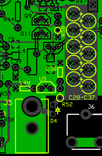
Mount the 2 4.7 uF ceramics first and watch out for C38: the silkscreen could lead you to believe it is horizontally oriented when it actually is vertically oriented (N-S) on the board.
Pay careful attention to the polarity of the electrolytic capacitors. The positive lead is usually the longer lead; the negative lead is on the side with the grey stripe and a minus sign.
The diode's polarity is also critical. Mount it such that the cathode end of the diode (with the stripe on it) is a hairpin lead into the square hole.
Resistor R50, while not part of the power supply circuit, is installed in this stage so as to provide a convenient (regular) ground point at its hairpin lead for the tests at the end of this stage and subsequent stages.
| Check | Designation | Component | Marking | Category | Orientation | Notes |
|---|---|---|---|---|---|---|
| ❏ | P1 | DC Power Plug 5.5/2.1mm Pos Ctr |
 | Plug | ||
| ❏ | D4 | 1N4003 | 1N4003
 | Axial | Mouint hairin style (barrel in round hole, hairpin lead in square hole) | |
| ❏ | C38 | 4.7 uF 10% 16V X7R RAD | 475
 | Ceramic | vert | |
| ❏ | C40 | 4.7 uF 10% 16V X7R RAD | 475
 | Ceramic | horiz | |
| ❏ | R52 | 68 1/6W 5% | bl-gry-blk-gld
 | 1/6W | N-S | (some kits may have 1/6W - this version is still OK) |
| ❏ | U09 | LM78L05 voltage regulator | LM78L05
 | TO-92 | Take ESD precautions | |
| ❏ | C28 | 10uF/16 VDC |
 | Electrolytic | ||
| ❏ | C29 | 10uF/16 VDC |
 | Electrolytic | ||
| ❏ | C30 | 10uF/16 VDC |
 | Electrolytic | ||
| ❏ | C31 | 10uF/16 VDC |
 | Electrolytic | ||
| ❏ | C32 | 10uF/16 VDC |
 | Electrolytic | ||
| ❏ | C33 | 10uF/16 VDC |
 | Electrolytic | ||
| ❏ | C34 | 10uF/16 VDC |
 | Electrolytic | ||
| ❏ | C35 | 10uF/16 VDC |
 | Electrolytic | ||
| ❏ | C36 | 10uF/16 VDC |
 | Electrolytic | ||
| ❏ | C37 | 10uF/16 VDC |
 | Electrolytic | ||
| ❏ | R50 | 22.1 k 1/4W 1% | r-r-brn-r-br
 | 1/4W | N-S | Installed and used as (regular) ground reference. |
| ❏ | J5 | DC Power Jack PCB Mount (rt-angle) |
 | Jack-RA |
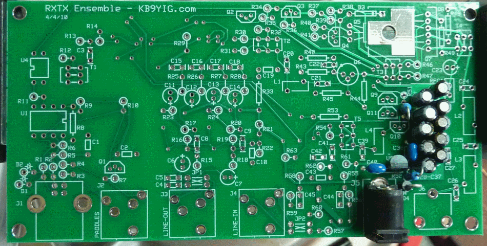
Power Supply Completed Stage
Top of the Board

Power Supply Testing
Current draw
Test Setup
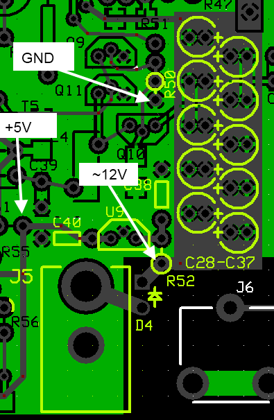
Before applying power for the first time, test the resistance across the 12V power rail (positive lead at the point marked for the non-hairpin end of R52; negative lead on a convenient ground (see diagram below)). You should see a very high resistance (over 50 k ohms) and it should climb (as the electrolytic capacitors charge up with the ohmmeter's voltage). Ultimately, you should see an extremely high (or infinite) resistance.
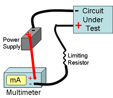
Once you have successfully passed the resistance test, put your mA meter in series with the input voltage positive line and measure the current draw of the power supply.
See Tutorial on Measuring Current for an illustration of how to measure current in a circuit.

Test Measurements
| Testpoint | Units | Nominal Value | Author's | Yours |
|---|---|---|---|---|
| Current draw | mA | < 8 | 4.5 | _______ |
Voltage Tests
Test Setup
Power up the board with a 12V supply (no limiting resistor) and measure the voltage at the test points indicated.
(Author's measurements below were taken using power from a gel cel whose voltage measured 12.9V)
Voltage measurements are WRT regular ground. For this test you can use the "hairpin" of R50 as a convenient regular ground test point.

Test Measurements
| Testpoint | Units | Nominal Value | Author's | Yours |
|---|---|---|---|---|
| Hairpin lead (hole) of R61 (wrt ground) | V dc | 5 (+/- 2%) | 4.94 | _______ |
| Hairpin lead of D4 (wrt ground) - (with 12.9 V gelcell) | V dc | 12 | 12.3 | _______ |