External Connections Introduction
General
Congratulations! You have successfully built and (unit) tested your Ensemble SDR transceiver for the chosen "super-band".
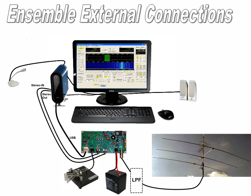
This is the wrap-up stage, where we connect the rig to the outside world (PC (SDR program and soundcard), antenna, and paddles and actually put the transceiver through it paces.
The builder may, at this point, want to consider the hardware and software offerings (PSDR-IQ and USB2SDR card) from Christos SV1EIA (sv1eia@gmail.com). This combination represents the best quality software and hardware interface between the computer and the Ensemble RXTX.
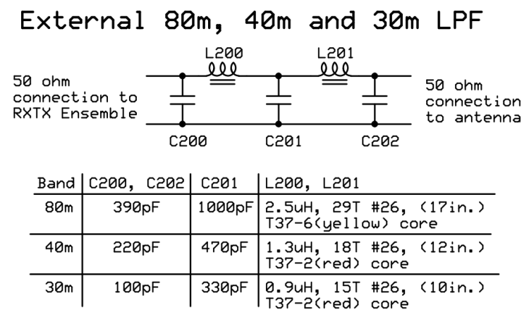
Depending upon the option you have chosen to build and how you wish to operate within that built option, you may need to provide additional low-pass filtering between the transceiver and the antenna. The FCC requires that the mean power of any spurious emission from a station transmitter or external RF amplifier transmitting on a frequency below 30 MHz must be at least 43 dB below the mean power of the fundamental emission. In the case of an 80m (3.5 MHz) transmitter, we must ensure that the mean power at the second harmonic (40m - 7.0 MHz) must be at least 43db below that of the fundamental 80m emission. This rule applies to the RXTX Ensemble. With the current design, the following options require low-pass filtering in order to reduce the second (and higher order) harmonics for the following options to at least 43 dB below that of the fundamental (first-mentioned) band (assuming you want to operate in that band):
| Band Option | Use LPF When Operating At | To Attenuate 2nd Harmonic At |
|---|---|---|
| 80/40m | (80m) 3.5 MHz | 7.0 MHz |
| 40/30/20m | (40m) 7.0 MHZ | 14 MHz |
| 30/20/17m | (30m)10.1 MHz | 20.2 MHz |
External Connections Schematic
(Resistor testpoints (hairpin, top, or left-hand lead), as physically installed on the board, are marked in the schematic with red dots)
(Click for Full Schematic)
(above schematic has clickable areas that can be used for navigation)
(go directly to build notes)External Connections Bill of Materials
Stage Bill of Materials
(resistor images and color codes courtesy of WIlfried, DL5SWB's R-Color Code program)
| Check | Count | Component | Marking | Category |
|---|---|---|---|---|
| ❏ | 1 | 4 X #4-40 hdw (nut, bolt, washer, spacer) |
 | HDW |
| ❏ | 7 | band-specific | misc |
Band Specific Items for 80, 40m Band
| Check | Designation | Component | Marking | Category | Orientation | Notes | Circuit |
|---|---|---|---|---|---|---|---|
| ❏ | C200 | 390 pF 5% | 391
 | Ceramic | External Connections | ||
| ❏ | C201 | 1000 pF 5% | 102
 | Ceramic | External Connections | ||
| ❏ | C202 | 390 pF 5% | 391
 | Ceramic | External Connections | ||
| ❏ | L200 | 2.5uH: 29T #26(17in) on T37-6 (yel) | yellow
 | Coil | External Connections | ||
| ❏ | L200-core | T37-6 toroid core | yellow
 | Toroid | External Connections | ||
| ❏ | L201 | 2.5uH: 29T #26(17in) on T37-6 (yel) | yellow
 | Coil | External Connections | ||
| ❏ | L201-core | T37-6 toroid core | yellow
 | Toroid | External Connections |
Band Specific Items for 40, 30, 20m Band
| Check | Designation | Component | Marking | Category | Orientation | Notes | Circuit |
|---|---|---|---|---|---|---|---|
| ❏ | C200 | 220 pF 5% | 221
 | Ceramic | External Connections | ||
| ❏ | C201 | 470 pF 5% | 471 | Ceramic | External Connections | ||
| ❏ | C202 | 220 pF 5% | 221
 | Ceramic | External Connections | ||
| ❏ | L200 | 1.3uH: 18T #26(12in) on T37-2(red) | red
 | coil | External Connections | ||
| ❏ | L200-core | T37-2 toroid core | red
 | Toroid | External Connections | ||
| ❏ | L201 | 1.3uH: 18T #26(12in) on T37-2(red) | red
 | coil | External Connections | ||
| ❏ | L201-core | T37-2 toroid core | red
 | Toroid | External Connections |
Band Specific Items for 30, 20, 17m Band
| Check | Designation | Component | Marking | Category | Orientation | Notes | Circuit |
|---|---|---|---|---|---|---|---|
| ❏ | C200 | 100 pF 5% | 101
 | Ceramic | External Connections | ||
| ❏ | C201 | 330 pF 5% | 331
 | Ceramic | External Connections | ||
| ❏ | C202 | 100 pF 5% | 101
 | Ceramic | External Connections | ||
| ❏ | L200 | 0.9uH: 15T #26(10 in) on T37-2 (red) | red
 | Coil | External Connections | ||
| ❏ | L200-core | T37-2 toroid core | red
 | Toroid | External Connections | ||
| ❏ | L201 | 0.9uH: 15T #26(10 in) on T37-2 (red) | red
 | Coil | External Connections | ||
| ❏ | L201-core | T37-2 toroid core | red
 | Toroid | External Connections |
External Connections Summary Build Notes
- Connect I and Q leads
- Connect USB
- Connect Antenna
- Connect Keyer
- Connect Power
- Install In Enclosure (Optional)
- Load and Run SDR Software
- Build and Connect External LPF
- Test the Stage
External Connections Detailed Build Notes
Top of the Board

Connect I and Q leads
Recently, there have been extensive discussions on the reflector concerning the fact that some builders have a combination of soundcard, software, PC, and operating system in which the jumpers/leads for the TX I and Q signals must be the reverse of the jumpers/leads for the RX I and Q. This has been pretty much a case-by-case experience. We are building a spreadsheet depicting various combinations of the relevant variables (soundcard, program, kit, PS, OS, etc.) and the wiring that "works" for the RX and TX I and Q signals.
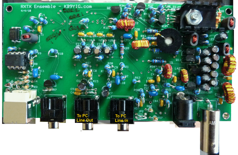
The IQ connections are via stereo cables, male-to-male, 1/8" plugs, connecting:
- "Line In" on the board to the "Line-In" (STEREO) input jack on the PC or sound card :
- "Line Out" on the board to the "Line-Out" (STEREO) output jack on the PC or sound card :
Install In Enclosure (Optional)
One possibility for a nice enclosure for this rig is the Specialty Bottle Rectangular, Windowed Tin.
Another - and a very nice one at that - is the enclosure offered by Tom KM5H on his website

Build and Connect External LPF
Note: if you intend to operate on 80m, 40m, or 30m, you MUST build special low-pass filters for those bands and connect it/them between your kit's antenna jack and the antenna. The LPFs are designed for the lowest freq band in the group ( 80 for the 80/40, 40 for the 40/30/20, and 30 for the 30/20/17 ). Thus, the external LPFs are built for and used in the antenna feed as follows:
- 80m LPF with the 80m/40m option.
- 40m LPF with the 40m/30m/20m option.
- 30m LPF with the 30m/30m/17m option.

| Check | Designation | Component | Marking | Category | Orientation | Notes | ||||||||||||
|---|---|---|---|---|---|---|---|---|---|---|---|---|---|---|---|---|---|---|
| ❏ | C200 | band-specific |
| misc | ||||||||||||||
| ❏ | C201 | band-specific |
| misc | ||||||||||||||
| ❏ | C202 | band-specific |
| misc | ||||||||||||||
| ❏ | L200 | band-specific |
| misc | ||||||||||||||
| ❏ | L200-core | band-specific | misc | |||||||||||||||
| ❏ | L201 | band-specific |
| misc | ||||||||||||||
| ❏ | L201-core | band-specific | misc |
External Connections Completed Stage
Top of the Board


