Power Supply Introduction
General
The RLC Meter is powered via a USB connection to an active USB port on a computer or powered hub. The USB (J3) connection provides 5 V dc, which is regulated by U3 to a fairly precise 3.3V dc. The 5V input to U3 is provided via 5 of the six available positions in the "B" gang of S1. The regulated 3.3V output from U3 is provided on the 3.3V rail (and causes the LED (D1) to light up when power is applied and all is working OK in the power supply.
(go directly to build notes)Power Supply Schematic
(Click for Full Schematic)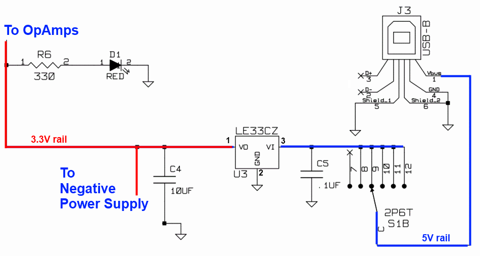
(above schematic has clickable areas that can be used for navigation)
(go directly to build notes)Power Supply Bill of Materials
Stage Bill of Materials
(resistor images and color codes courtesy of WIlfried, DL5SWB's R-Color Code program)
| Check | Designation | Component | Marking | Category | Orientation | Notes | Circuit |
|---|---|---|---|---|---|---|---|
| ❏ | cbl1 | USB-A to USB-B Cable | User-Supplied | Not furnished with kit. | Power Supply | ||
| ❏ | D1 | red LED |
 | LED | Power Supply | ||
| ❏ | S1 | 2 pole six pos rotary switch |
 | 2P6T | Power Supply | ||
| ❏ | U3 | LE33CZ 3.3V voltage regulator |
 | TO-92 | Power Supply | ||
| ❏ | C5 | 100 nF(0,1 uF) | 104
 | Ceramic | Leave enough space between the bottom of the cap and the top of the board to allow your DMM probe to get in and touch the lower lead. | Power Supply | |
| ❏ | C4 | 10 uF | 106
 | tantalum | Power Supply | ||
| ❏ | J3 | USB-B pcb jack (rt-angle) |
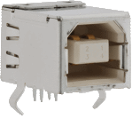 | Jack-RA | Power Supply | ||
| ❏ | R6 | 330 1/4W 5% | ora-ora-brn-gld
 | 1/4W | Power Supply |
Power Supply Summary Build Notes
- Install Voltage Regulator
- Install Capacitors
- Install Diode and limiting Resistor
- Install Rotary Switch
- Test the Stage
Power Supply Detailed Build Notes
Top of the Board
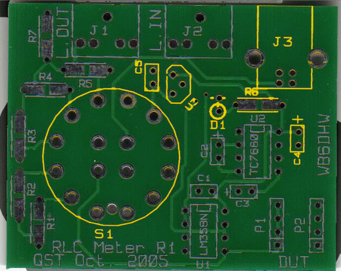
Install Voltage Regulator
Mount the USB jack to the board
Mount the voltage regulator, U3, upright in the holes provided
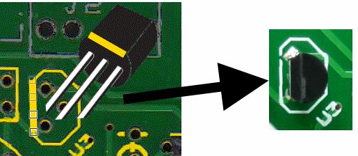
Note the orientation of the U3 IC: align the flat side with the corresponding flat side on the board's silkscreen. The graphic show the alignment of the flat side with the silkscreen marking. Note the transistor must be mounted so that it stands up vertically (not laying down as the graphic might suggest.
| Check | Designation | Component | Marking | Category | Orientation | Notes |
|---|---|---|---|---|---|---|
| ❏ | cbl1 | USB-A to USB-B Cable | User-Supplied | Not furnished with kit. | ||
| ❏ | U3 | LE33CZ 3.3V voltage regulator |
 | TO-92 | Take ESD precautions | |
| ❏ | J3 | USB-B pcb jack (rt-angle) |
 | Jack-RA |
Install Capacitors
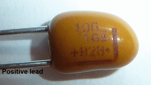
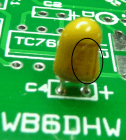
Tantalum capacitors are polarized. Take care to align the tantalum capacitor for correct polarity (see graphic) The positive lead should go to the hole marked "+".
| Check | Designation | Component | Marking | Category | Orientation | Notes |
|---|---|---|---|---|---|---|
| ❏ | C5 | 100 nF(0,1 uF) | 104
 | Ceramic | Leave enough space between the bottom of the cap and the top of the board to allow your DMM probe to get in and touch the lower lead. | |
| ❏ | C4 | 10 uF | 106
 | tantalum |
Install Diode and limiting Resistor
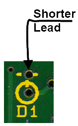
Note the orientation of the LED. The cathode lead is the shorter of the 2 leads.
Some LEDs will also have a flat edge/bevel in the ring around the bottem of the LED to signify the cathode lead.
| Check | Designation | Component | Marking | Category | Orientation | Notes |
|---|---|---|---|---|---|---|
| ❏ | D1 | red LED |
 | LED | ||
| ❏ | R6 | 330 1/4W 5% | ora-ora-brn-gld
 | 1/4W |
Install Rotary Switch
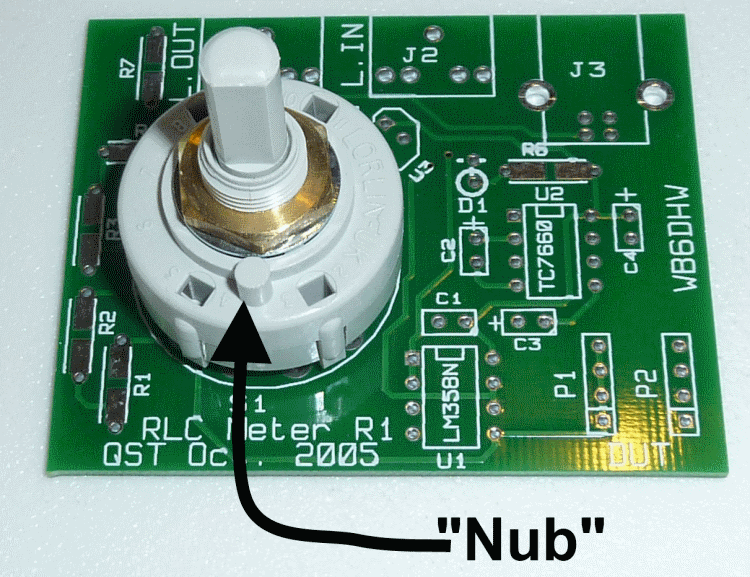
Take care to orient the rotary switch so the round "nub" is at the 6 o'clock position.
Hint: to facilitate soldering, you should place the switch pins into their respective holes, then, holding the switch firmly to the board, turn the board over and "tack solder" two opposite pins using a blob of solder on the iron. Once the switch has been "tacked", just to be sure, turn the board over and check for correct orientation, before returning to the bottom side and soldering the remaining pins (and resoldering the "tack solder" joints).
| Check | Designation | Component | Marking | Category | Orientation | Notes |
|---|---|---|---|---|---|---|
| ❏ | S1 | 2 pole six pos rotary switch |
 | 2P6T |
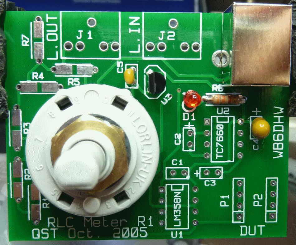
Power Supply Completed Stage
Top of the Board
Power Supply Testing
Power On/Off Switching
Test Setup
Connect the USB Jack (J3) to a powered USB port on your computer (or a powered hub).
Rotate the switch (S1) clockwise through its positions and verify that the LED lights up in five of the 6 possible S1 positions
(This verifies that the voltage regulator has received the 5V from the USB port, regulated it down to 3.3V and passed it on to the LED. If you do not get the LED to light up on any of the positions, then check back through the circuit to the voltage regulator and measure its input voltage - see next test..
Test Measurements
| Testpoint | Units | Nominal Value | Author's | Yours |
|---|---|---|---|---|
| left-most position (most counterclockwise) of S1 | LED | OFF | OFF | _______ |
| All other positions of S1 | LED | ON | ON | _______ |
Voltage Regulator Output and Input
Test Setup
With board connected to powered USB port:
Rotate S1 to a position where the red LED lights up.
All voltage measurements in this stage are with respect to ground ("WRT Ground").
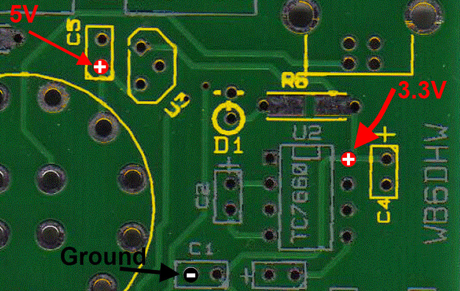
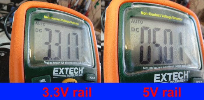
Measure the voltage at the 3.3V testpoint. If the voltage regulator is working correctly, you should see a voltage at or very close to 3.3V dc.
When using the 5V testpoint (lower lead of C5), take great care not to short the leads of C5 together. Doing this would short the +5V directly to ground, with unpleasant consequences not limited just to SSZ (smoking, sparking, and zapping).
Test Measurements
| Testpoint | Units | Nominal Value | Author's | Yours |
|---|---|---|---|---|
| 3.3V testpoint (see graphic) | V dc | 3.3 | 3.31 | _______ |
| 5V testpoint (Careful! Do not short C5's leads) | V dc | 5 | 5.01 | _______ |