Negative Power Supply Introduction
General
Once the powersupply is working, we need to provide a negative reference voltage that the OpAmps in the final stage can use. This is accomplished with U2 which takes the 3.3V dc from the power supply and outputs a negative 3.3V dc voltage.
(go directly to build notes)Negative Power Supply Schematic
(Click for Full Schematic)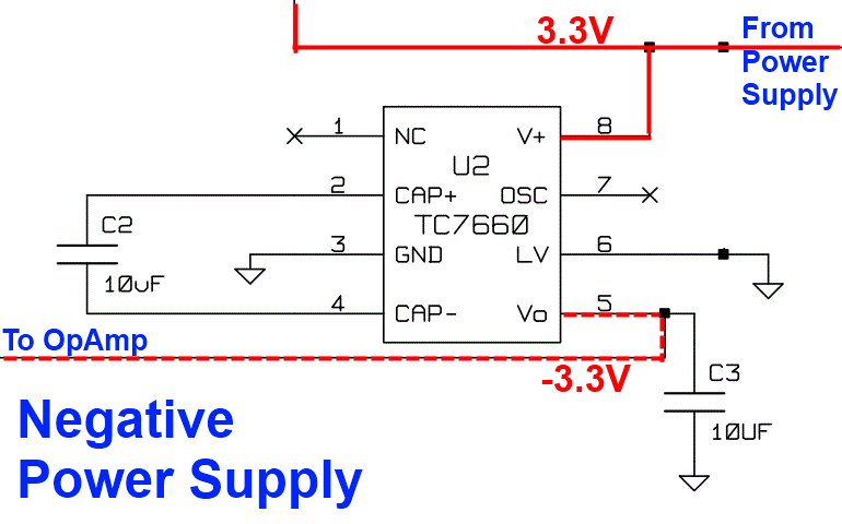
(above schematic has clickable areas that can be used for navigation)
(go directly to build notes)Negative Power Supply Bill of Materials
Stage Bill of Materials
(resistor images and color codes courtesy of WIlfried, DL5SWB's R-Color Code program)
| Check | Designation | Component | Marking | Category | Orientation | Notes | Circuit |
|---|---|---|---|---|---|---|---|
| ❏ | U2 | TC7660 charge Pump DC-DC Conv |
 | DIP-8 | Negative Power Supply | ||
| ❏ | C2 | 10 uF | 106
 | tantalum | Negative Power Supply | ||
| ❏ | C3 | 10 uF | 106
| tantalum | Negative Power Supply |
Negative Power Supply Summary Build Notes
- Install U2
- Install the two Tantalum (polarized) Capacitors
- Test the Stage
Negative Power Supply Detailed Build Notes
Top of the Board
Install U2
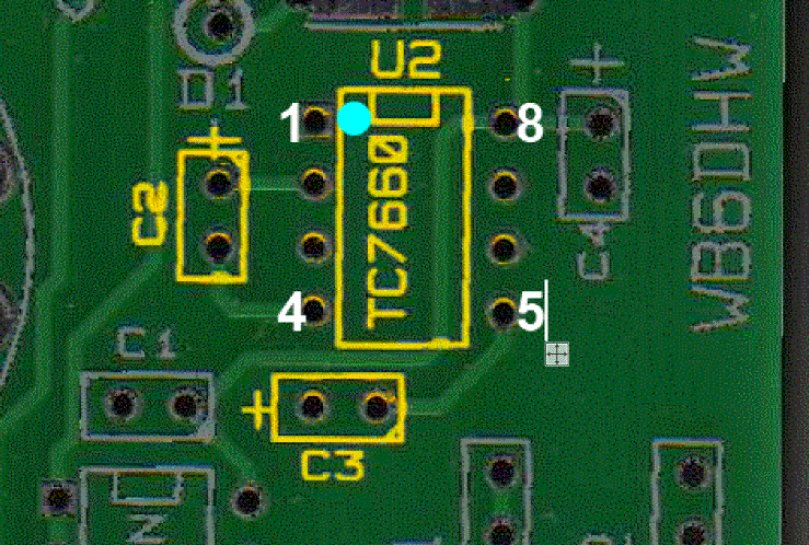
Take care installing U2. In addition to its sensitivity to electrostatic discharge (ESD), we want to be very careful to orient the chip correctly. The chip will have a dimple on it denoting the location of pin 1.
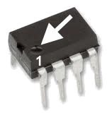
Insert the chip into the holes using the dimple and the graphic herein to ensure that pin 1 is correctly aligned.
"Tack Solder" two opposite pins to hold the chip in. Then turn the board over from the bottomside to the topside and DOUBLE CHECK YOUR WORK before soldering, then, CHECK AGAIN. You do not want to have to remove the chip because it was improperly oriented!
Be sure to verify that all 8 pins went through their respective holes. If one of the pins gets folded under during insertion, it is nearly impossible to detect and can lead to a frustrating trouble-shooting experience.
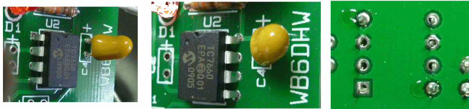
Once you are certain of the correct orientation and all pins are through the holes, turn the board over to the bottomside and solder all of the pins.
| Check | Designation | Component | Marking | Category | Orientation | Notes |
|---|---|---|---|---|---|---|
| ❏ | U2 | TC7660 charge Pump DC-DC Conv |
| DIP-8 | Take ESD precautions |
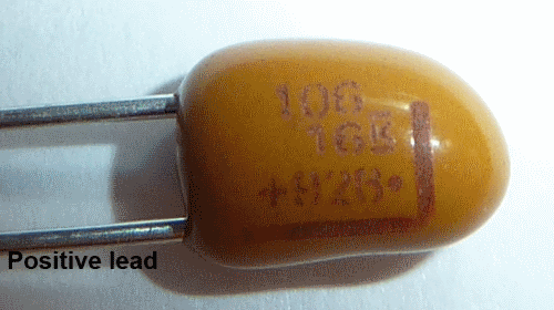
Install the two Tantalum (polarized) Capacitors
Be sure to install these with the correct orientation and polarity. The positive lead of the cap must align with the "+" sign on the silkscreen.
| Check | Designation | Component | Marking | Category | Orientation | Notes |
|---|---|---|---|---|---|---|
| ❏ | C2 | 10 uF | 106
| tantalum | ||
| ❏ | C3 | 10 uF | 106
| tantalum |
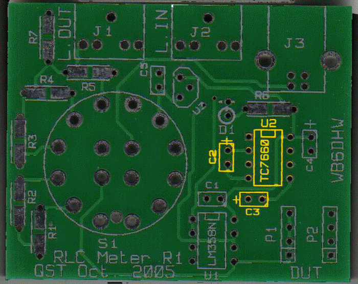
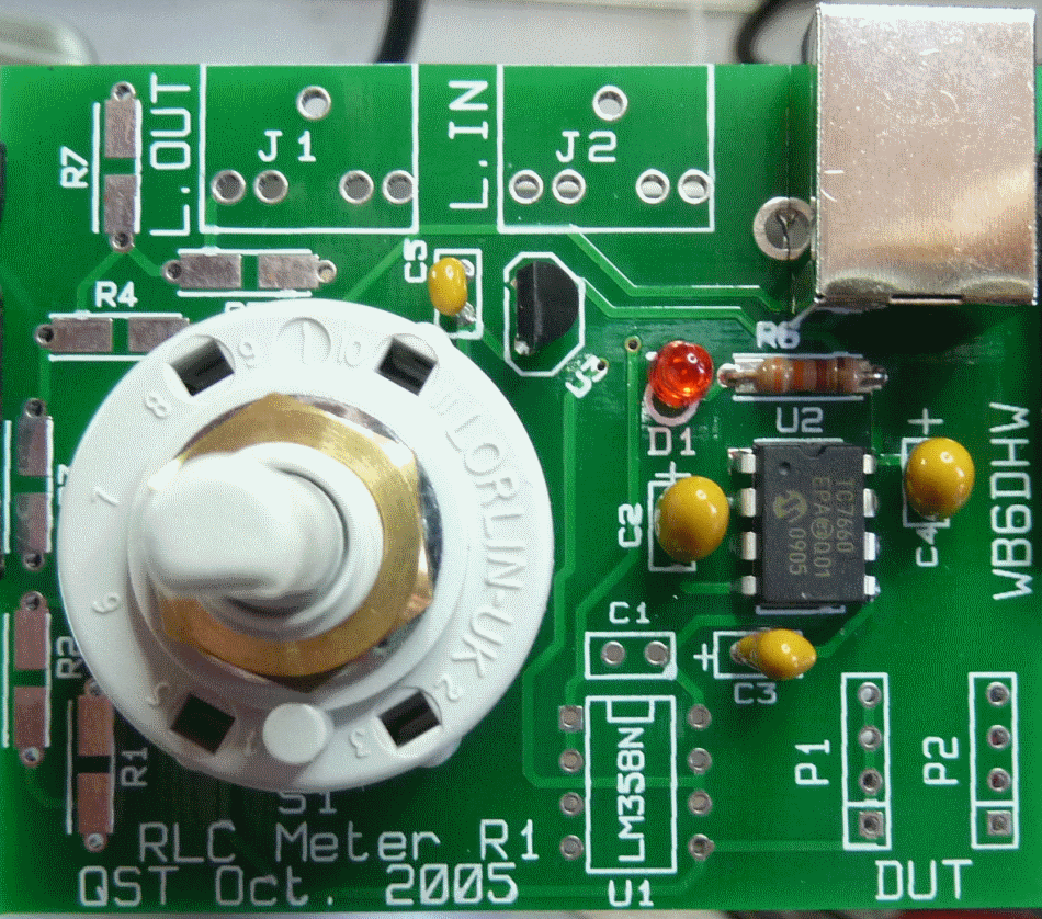
Negative Power Supply Completed Stage
Top of the Board
Negative Power Supply Testing
Voltage Test
Test Setup
Power up the board via the USB cable
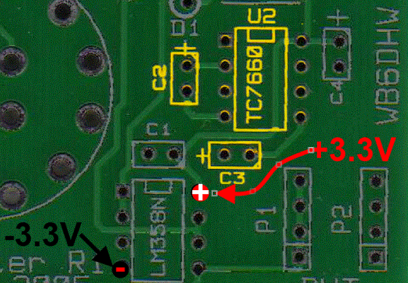
Measure the voltage at the "-3,3V" testpoint, with respect to ground
Measure the voltage at the "+"3.3V" testpoint, with respect to ground.
You can use any of the holes on P2 as a ground reference.
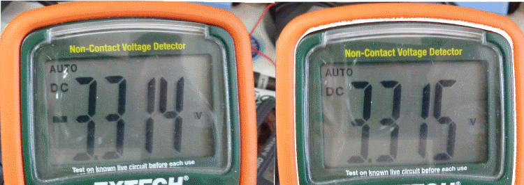
Test Measurements
| Testpoint | Units | Nominal Value | Author's | Yours |
|---|---|---|---|---|
| "- 3.3V" (WRT ground) | V dc | - 3.3 | 3.315 | _______ |
| "+ 3.3V" (WRT ground) | V dc | +3.3 | 3.314 | _______ |