Local Oscillator/Control Introduction
General
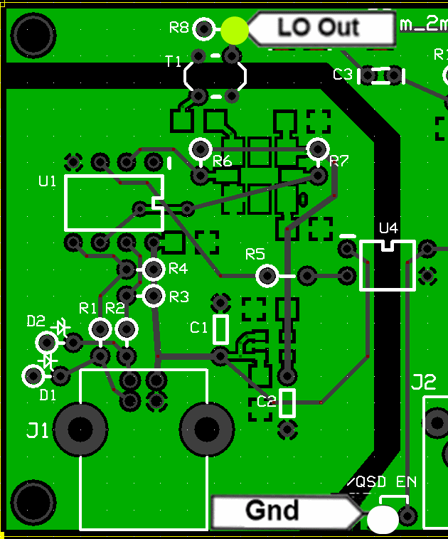
This stage completes the component installation for the isolated USB ground plane and implements the microcontroller and programmable local oscillator functionality.
The microcontroller implements a USB device which can control frequency of the programmable oscillator (Si570). Depending upon the VHF band selected (6m, 4m, or 2m) the frequency provided will be determined by a special, band-specific multiplier in the microprocessor. Refer to the Theory Section of the Home page for details on the process of generating the appropriate frequency.
The signal output from this stage will be consumed by two other stages:
- The Quadrature Clock Generator (dividing by 4 and outputting two resultant signals in quadrature)
- The RF/Control Stage (using the signal as a local Oscillator frequency input (along with the pre-amplified RF signal from the antenna) into a double balanced mixer.
Local Oscillator/Control Schematic
(Resistor testpoints (hairpin, top, or left-hand lead), as physically installed on the board, are marked in the schematic with red dots)
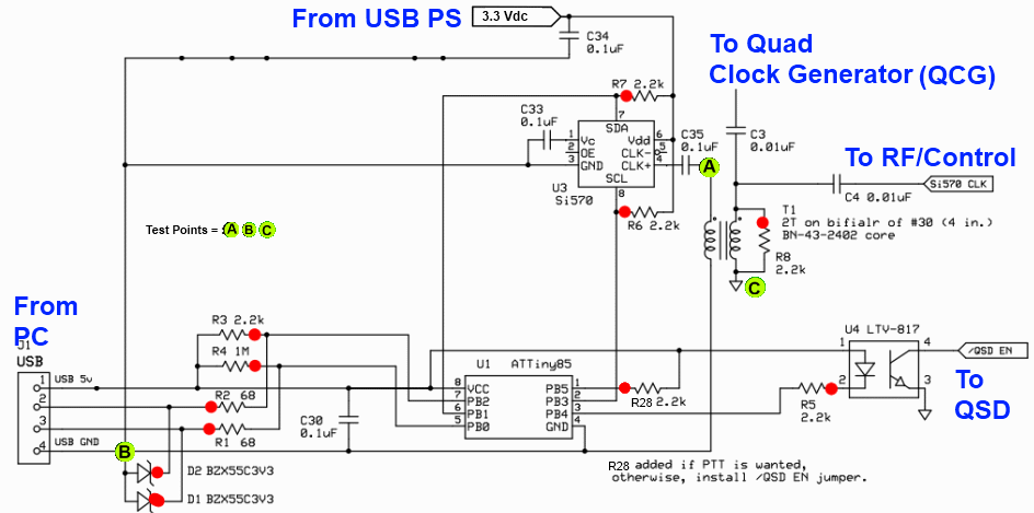
(above schematic has clickable areas that can be used for navigation)
(go directly to build notes)Local Oscillator/Control Bill of Materials
Stage Bill of Materials
(resistor images and color codes courtesy of WIlfried, DL5SWB's R-Color Code program)
| Check | Designation | Component | Marking | Category | Orientation | Notes | Circuit |
|---|---|---|---|---|---|---|---|
| ❏ | magwire30_8in | Magnetic Wire, enameled #30 | Magnetic | Local Oscillator/Control | |||
| ❏ | SO1 | 8 pin dip socket | Socket | Local Oscillator/Control | |||
| ❏ | T01 | 2T Bifilar #30 (4") on BN-43-2402 |
 | Xfrmr | Local Oscillator/Control | ||
| ❏ | T01-core | BN-43-2402 (no markings!) | none
 | Binocular core | Local Oscillator/Control | ||
| ❏ | U03 | Si570 Programmable Oscillator | SiLabs 570
 | I2C | Local Oscillator/Control | ||
| ❏ | C03 | 0.01 uF | 103
 | Ceramic | Local Oscillator/Control | ||
| ❏ | C04 | 0.01 uF | 103
 | Ceramic | Local Oscillator/Control | ||
| ❏ | C30 | 0.1 uF | (smt) black stripe
 | SMT 1206 | Local Oscillator/Control | ||
| ❏ | C33 | 0.1 uF | (smt) black stripe
 | SMT 1206 | Local Oscillator/Control | ||
| ❏ | C34 | 0.1 uF | (smt) black stripe
 | SMT 1206 | Local Oscillator/Control | ||
| ❏ | C35 | 0.1 uF | (smt) black stripe
 | SMT 1206 | Local Oscillator/Control | ||
| ❏ | U04 | LTV-817 Opto-Isolator | LTV 817
 | DIP-4 | Local Oscillator/Control | ||
| ❏ | U01 | ATtiny 85-20 PU w/V15.12 Firmware | AVR ATTINY85-20PU
 | DIP 8 | Local Oscillator/Control | ||
| ❏ | R01 | 68 1/6W 5% | bl-gry-blk-gld
 | 1/6W | Local Oscillator/Control | ||
| ❏ | R02 | 68 1/6W 5% | bl-gry-blk-gld
 | 1/6W | Local Oscillator/Control | ||
| ❏ | R03 | 2.2k 1/6W 5% | red-red-red-gld
 | 1/6W | Local Oscillator/Control | ||
| ❏ | R05 | 2.2k 1/6W 5% | red-red-red-gld
 | 1/6W | Local Oscillator/Control | ||
| ❏ | R06 | 2.2k 1/6W 5% | red-red-red-gld
 | 1/6W | Local Oscillator/Control | ||
| ❏ | R07 | 2.2k 1/6W 5% | red-red-red-gld
 | 1/6W | Local Oscillator/Control | ||
| ❏ | R08 | 2.2k 1/6W 5% | red-red-red-gld
 | 1/6W | Local Oscillator/Control | ||
| ❏ | R28 | 2.2k 1/6W 5% | red-red-red-gld
 | 1/6W | Not needed if ABPF is enabled in CFGSR for U1 | Local Oscillator/Control | |
| ❏ | R04 | 1 M 1/6W 5% | brn-blk-grn-gld
 | 1/6W | Local Oscillator/Control | ||
| ❏ | D01 | BZX55C3V3 3.3V zener diode | BZX55C
 | Axial | Local Oscillator/Control | ||
| ❏ | D02 | BZX55C3V3 3.3V zener diode | BZX55C
 | Axial | Local Oscillator/Control |
Local Oscillator/Control Summary Build Notes
- Install Protective Topside Parts
- Install Si570 Programmable Oscillator
- Install SMT Caps
- Wind and Install T1 and Associated Components
- Install Remaining Resistors and Zener Diodes
- Install U1 Socket
- Install U4 and Plug in U1
- Test the Stage
Local Oscillator/Control Detailed Build Notes
Bottom of the Board
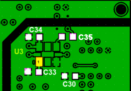
Install Protective Topside Parts
Install these resistors first, so as to protect against solder splashover at pins 4 and 8 off the Si570 (see below)
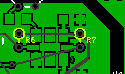
| Check | Designation | Component | Marking | Category | Orientation | Notes |
|---|---|---|---|---|---|---|
| ❏ | R06 | 2.2k 1/6W 5% | red-red-red-gld
 | 1/6W | ||
| ❏ | R07 | 2.2k 1/6W 5% | red-red-red-gld
 | 1/6W |
Install Si570 Programmable Oscillator
Tin the eight pads for the si570
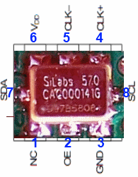
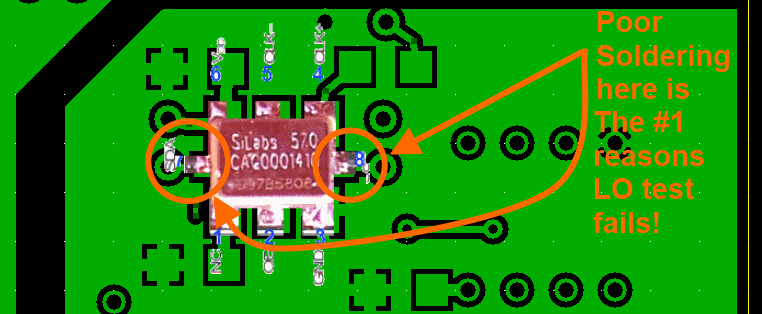
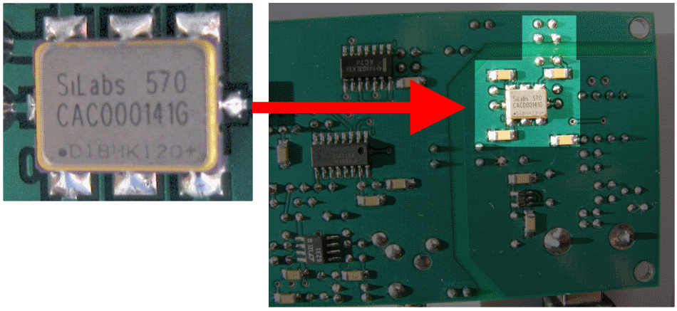
Align the Si570 as shown in the graphic below and solder the 1 pin. Verify that alignment is still good (adjusting and resoldering pin 1 until it is) and then solder the remaining seven pins.
Carefully examine the soldering under bright light and magnification. Most builders' Si570 problems can be traced to soldering defects, especially on the two end poins (pins 7 and 8) or to soldering in incorrect orientation
| Check | Designation | Component | Marking | Category | Orientation | Notes |
|---|---|---|---|---|---|---|
| ❏ | U03 | Si570 Programmable Oscillator | SiLabs 570
 | I2C | Take ESD precautions |
Install SMT Caps
Solder the four SMT Caps - all 0.1 uF
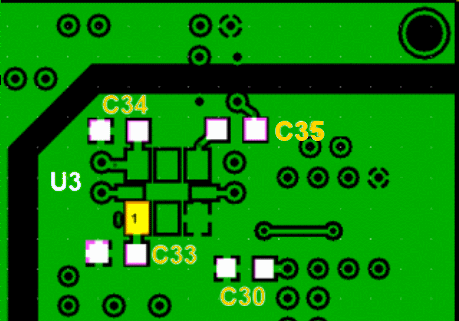
| Check | Designation | Component | Marking | Category | Orientation | Notes |
|---|---|---|---|---|---|---|
| ❏ | C30 | 0.1 uF | (smt) black stripe
 | SMT 1206 | ||
| ❏ | C33 | 0.1 uF | (smt) black stripe
 | SMT 1206 | ||
| ❏ | C34 | 0.1 uF | (smt) black stripe
 | SMT 1206 | ||
| ❏ | C35 | 0.1 uF | (smt) black stripe
 | SMT 1206 |
Top of the Board
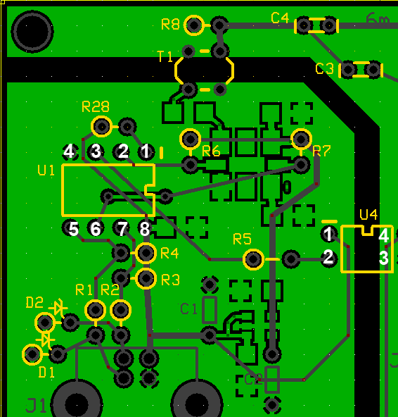
Wind and Install T1 and Associated Components
You should take two 5" strands of #30 wire and twist them together ("bifilar") so you get around 3 twists to the inch. Using the resultant bifilar strand, thread it through the binocular core for two turns. Remember a turn is a trip that:
- starts at a particular hole
- goes into that hole and out of the other end
- goes into the hole nthat is across from the hole out of which it just exited, and
- Comes out of the hole at the opposite end and across from the original entry hole.
Do that series twice with the twisted pair and you have a transformer with two windings (each winding corresponding to one of the two twisted single wires). Each winding (primary and secondary) is two turns. Since the windings are identical in length and number of turns, you can arbitratily pick either one as the primary, with the remaining winding serving as the secondary winding.
(Hint: use an ohmmeter (or other continuity checker) to identify which wire-ends go together to make the ends of a winding.
The board layout error on the 6m/4m/2m RX Ensemble board where either the primary or secondary leads of T1 needed to be crossed for best performance has now been corrected with the latest 6m/4m/2m RX Ensemble circuit board. The new circuit board, now supplied in 6m/4m/2m RX Ensemble kits, has the date 9/8/12 in the silkscreen printing on the top surface of the board.

| Check | Designation | Component | Marking | Category | Orientation | Notes |
|---|---|---|---|---|---|---|
| ❏ | magwire30_8in | Magnetic Wire, enameled #30 | Magnetic | |||
| ❏ | T01 | 2T Bifilar #30 (4") on BN-43-2402 |
 | Xfrmr | ||
| ❏ | C03 | 0.01 uF | 103
 | Ceramic | ||
| ❏ | C04 | 0.01 uF | 103
 | Ceramic | ||
| ❏ | R08 | 2.2k 1/6W 5% | red-red-red-gld
 | 1/6W |
Install Remaining Resistors and Zener Diodes
R28 is only needed if you disable ABPF and choose the option to have PTT control of the Quadrature Sampling Detector's enabling. We have chosen to NOT implement that capability in this documentation.
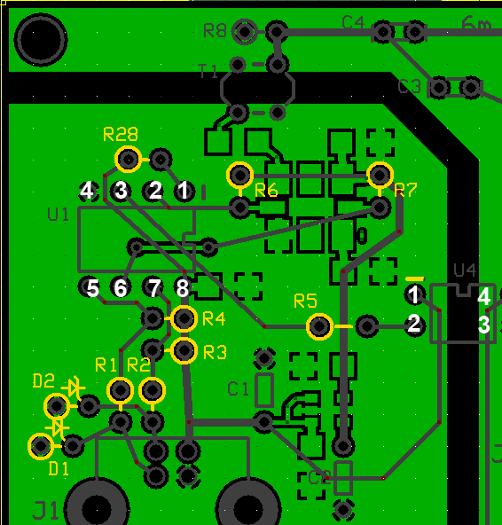
| Check | Designation | Component | Marking | Category | Orientation | Notes |
|---|---|---|---|---|---|---|
| ❏ | R01 | 68 1/6W 5% | bl-gry-blk-gld
 | 1/6W | ||
| ❏ | R02 | 68 1/6W 5% | bl-gry-blk-gld
 | 1/6W | ||
| ❏ | R03 | 2.2k 1/6W 5% | red-red-red-gld
 | 1/6W | ||
| ❏ | R05 | 2.2k 1/6W 5% | red-red-red-gld
 | 1/6W | ||
| ❏ | R28 | 2.2k 1/6W 5% | red-red-red-gld
 | 1/6W | Not needed if ABPF is enabled in CFGSR for U1 | |
| ❏ | R04 | 1 M 1/6W 5% | brn-blk-grn-gld
 | 1/6W | ||
| ❏ | D01 | BZX55C3V3 3.3V zener diode | BZX55C
 | Axial | ||
| ❏ | D02 | BZX55C3V3 3.3V zener diode | BZX55C
 | Axial |
Install U1 Socket
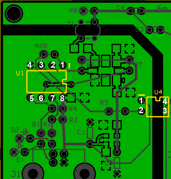
| Check | Designation | Component | Marking | Category | Orientation | Notes |
|---|---|---|---|---|---|---|
| ❏ | SO1 | 8 pin dip socket | Socket |
Install U4 and Plug in U1
Some builders may opt to use a socket (not provided in the kit) for mounting U4, although it is not required. If you install U4 without a socket, double check the orientation, as removal post-soldering is not fun!
| Check | Designation | Component | Marking | Category | Orientation | Notes |
|---|---|---|---|---|---|---|
| ❏ | U04 | LTV-817 Opto-Isolator | LTV 817
 | DIP-4 | Take ESD precautions | |
| ❏ | U01 | ATtiny 85-20 PU w/V15.12 Firmware | AVR ATTINY85-20PU
 | DIP 8 | Take ESD precautions |
Local Oscillator/Control Completed Stage
Top of the Board
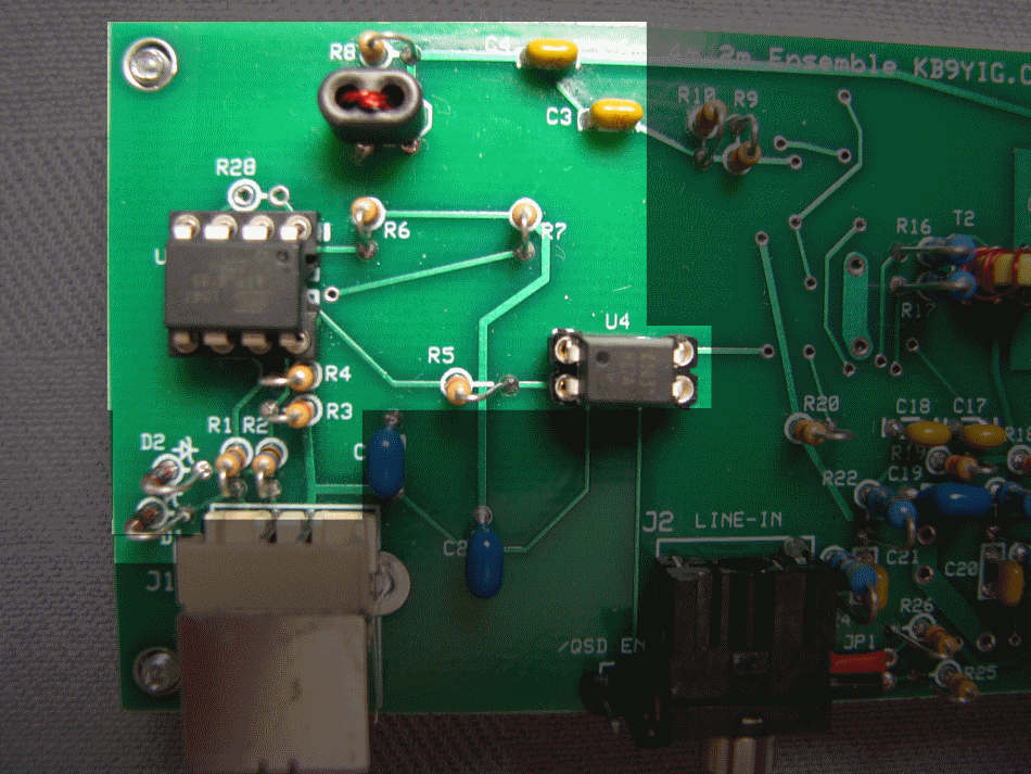
Bottom of the Board
Local Oscillator/Control Testing
Current Draw
Test Setup
Power up the regular circuit side of the board
Measure the current draw on the 12 V power lead (WITHOUT the USB plugged in)
Plug in the USB cable and keep 12V power to the main circuit
Measure the current draw on the 12 V power lead (WITH the USB plugged in). You should get a slightly higher current draw.
Test Measurements
| Testpoint | Units | Nominal Value | Author's | Yours |
|---|---|---|---|---|
| Current Draw - NO USB | mA | < 8 | 4.3 | _______ |
| Current Draw - USB plugged in | mA | < 9 | 5.3 | _______ |
Continuity Test T1 Windings
Test Setup
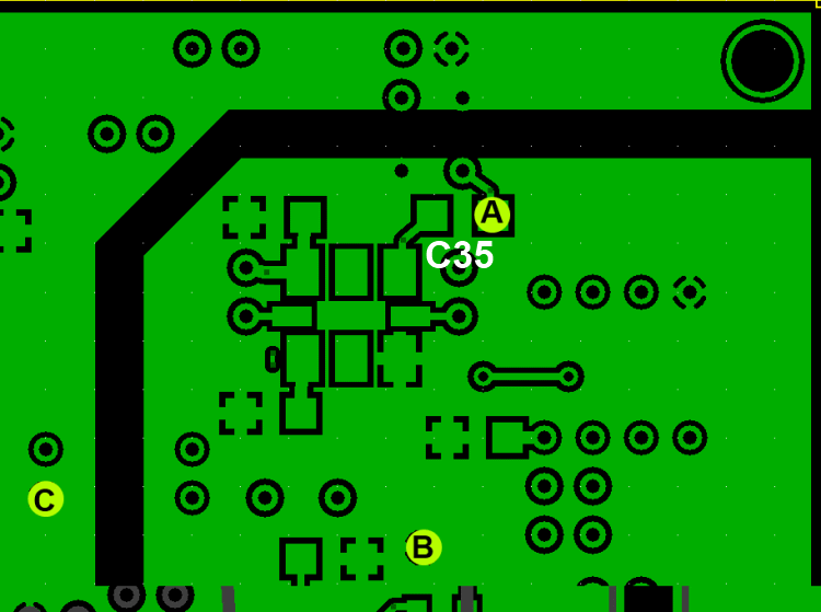
Using an ohmmeter, check for continuity between the right-hand pad for C35 (point marked "A" - junction of C35 and T1-Primary winding) and the USB ground plane (point marked "B" - where C1 goes to USB ground plane). You should get continuity (~ 0 ohms).
Then, check for continuity (~ 0 ohms) between the right-hand pad of C35 (point marked "A") and the regular ground (point marked "C" - where pin 3 of U4 goes to the regular circuit ground). You should NOT get continuity; if you do get continuity, then you have a short in the windings or you have your windings crossed.
These testpoints are indicated on the schematic diagram at the top of this page and are identified so as to allow testing for continuity through the soldered joints of the coil winding.
Test Measurements
| Testpoint | Units | Nominal Value | Author's | Yours |
|---|---|---|---|---|
| Point "A" to Point "B" | continuity | YES | yes | _______ |
| Point "A" to Point "C" | continuity | NO | no | _______ |
LO Output
Test Setup
Here we want to measure the output (4x center frequency for dividers). It is measured WRT (regular) ground (at the R8 hairpion lead).
Be sure all software and drivers, etc., have been installed. Connect the USB jack via USB cable to the PC. You should hear the "BoopBoop" sound the PC makes when it recognizes a device (the Ensemble) has been attached to a USB port..
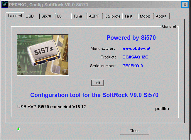
Next, run CFGSR.exe and you should get the following screen:
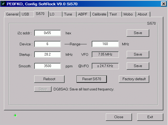
Then, check out the "Si570" tab. It should look like this:
Note that the Local Oscillator's outputs are measured with respect to the analog ground plane, NOT with respect to the galvanically isolated USB groundplane. The "/QSD EN" shunt is a good point for this ground connection.
Using the CFGSR Software (at the "Tune" tab), test scenarios for setting the center frequency (remember, the Si570 produces a signal that is 4 times the desired center frequency).
Measure the output at the hairpin lead of R8.
Below is an example of tuning the Si570 in CFGSR, selecting a center frerquency of 1.53 MHz (with an Si570 output frequency of 4x, or 6.12MHz. (Pay no attention to the lousy oscilloscope behind the curtains - the output is really a square wave, but the scope is a cheap USB scope that doesn't sample HF square waves very well.)
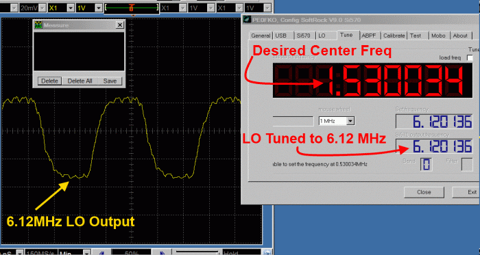
You can place your mouse on the frequency in the center frequency field and turn your mouse wheel. The center frequency will increase or decrease and the LO Output frequency (4x) will increase or decrease at a rate 4 times that of the center frequency.
John, KB6QL, discovered this trick for those with no scope, counter, or HF radio to use in testing LO output:
"Turns out that local oscillator can be tuned for a frequency that is in the FM band. So, as a quick and dirty, I got out my little MP3 player-cum-FM-radio and tuned it to that frequency and let the headset cord/ant drape over the RX. It gave me full quieting. Then I switched the RX to another frequency and the quieting was gone."
Troubleshooting
Frequency Will Not Change
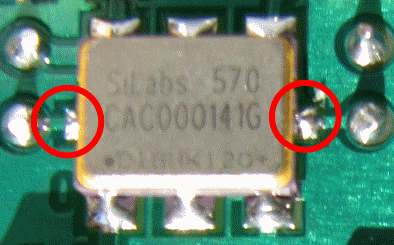
If the Si570 is putting out its default frequency, but does not respond to commands to shange the frequency, the most likely culprit is the soldering of pins 7 and 8 (on the long ends of the chip. Double check the soldering.
