RF Front End Introduction
General
This stage begins at the VHF antenna. The incoming VHF RF signal is preamplified and filtered and presented as the "RF" signal to the ADE + Double Balanced Mixer (DBM). That mixer also accepts the Local Oscillator's output (BEFORE the Quadrature Clock Generator) as the "LO" input. The two signals, "RF" and "LO" are then mixed to result in the "IF" output of the DBM. This output contains the sum and difference products of mixing the two inputs. The sum component is filtered out, sending the difference component into the Quadrature Sampling Detector (QSD) stage.
For example, assume that the VHF signal of interest is at a frequency of 145.200 MHz. Thanks to the firmware in the on-board microcontroller in the LO stage, the LO will produce an output of 116.16 MHz. The DBM accepts the preamplified and filtered incoming RF signal at 145.200 MHz along with the LO signal of 116.16 MHz, to produce a signal with sum and difference components:
- 261.36 MHz (Σ)
- 29.04 MHz (Δ)
The sum (Σ) is discarded and the difference (Δ = 29.04 MHz) is sent to the QSD stage. If the SDR software was configured to set the center frequency at 145.200 MHz, then it would manifest itself in the QSD as 29.04 MHz.
In the above example, then, an incoming RF VHF signal of 145.210 MHz would mix down to a QSD input of 29.05 MHz, 10 kHz above the center frequency.
(
go directly to build notes)
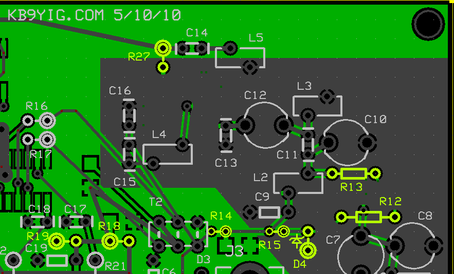
RF Front End Schematic
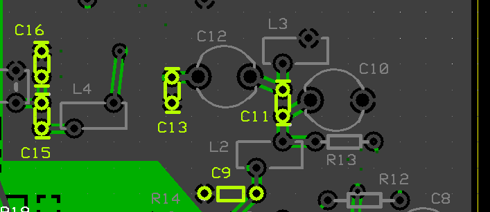
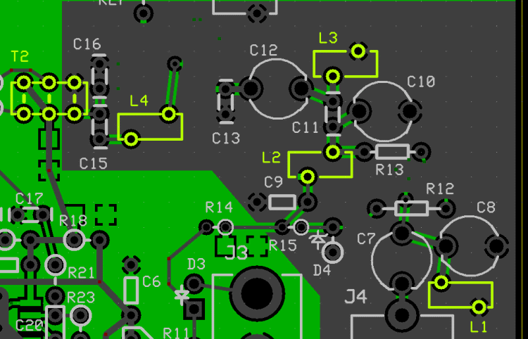
(Resistor testpoints (hairpin, top, or left-hand lead), as physically installed on the board, are marked in the schematic with red dots)
(above schematic has clickable areas that can be used for navigation)
(
go directly to build notes)
RF Front End Bill of Materials
Stage Bill of Materials
(resistor images and color codes courtesy of WIlfried, DL5SWB's R-Color Code program)
| Check | Designation | Component | Marking | Category | Orientation | Notes | Circuit |
|---|
| ❏ | C07 | band-specific | | misc | | | RF Front End |
| ❏ | C11 | band-specific | | misc | | | RF Front End |
| ❏ | C13 | band-specific | | misc | | | RF Front End |
| ❏ | C14 | unused capacitor | | Unused | | | RF Front End |
| ❏ | C15 | band-specific | | misc | | | RF Front End |
| ❏ | C16 | band-specific | | misc | | | RF Front End |
| ❏ | D04 | 1N5227B | 1N5227B | Axial | | | RF Front End |
| ❏ | J04 | BNC Connector Male - PCB mount |
 | Jack | | | RF Front End |
| ❏ | L01 | band-specific | | misc | | | RF Front End |
| ❏ | L01_core | band-specific | | misc | | | RF Front End |
| ❏ | L02 | band-specific | | misc | | | RF Front End |
| ❏ | L02_core | band-specific | | misc | | | RF Front End |
| ❏ | L03 | band-specific | | misc | | | RF Front End |
| ❏ | L03_core | band-specific | | misc | | | RF Front End |
| ❏ | L04 | band-specific | | misc | | | RF Front End |
| ❏ | L04_core | band-specific | | misc | | | RF Front End |
| ❏ | L05 | unused inductor | | Coil | | | RF Front End |
| ❏ | L05_core | unused inductor | | Coil | | | RF Front End |
| ❏ | Magwire26_31in | Magnetic Wire, enameled #26 | | Magnetic | | | RF Front End |
| ❏ | magwire30_40in | Magnetic Wire, enameled #30 | | Magnetic | | | RF Front End |
| ❏ | T02 | band-specific | | misc | | | RF Front End |
| ❏ | T02-core | band-specific | | misc | | | RF Front End |
| ❏ | C08 | trimmer capacitor 30 pF | green
 | Trimmer | | | RF Front End |
| ❏ | C10 | trimmer capacitor 30 pF | green
| Trimmer | | | RF Front End |
| ❏ | C12 | trimmer capacitor 30 pF | green
| Trimmer | | | RF Front End |
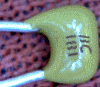
| ❏ | C09 | 4.7 uF 10% 16V X7R RAD | 475
 | Ceramic | | | RF Front End |
| ❏ | R13 | 33 1/6W 5% | ora-ora-blk-gld
 | 1/6W | | | RF Front End |
| ❏ | R27 | 47 1/6W 5% | yel-vio-blk-gld
 | 1/6W | | | RF Front End |
| ❏ | R14 | 120 1/6W 5% | brn-red-brn-gld
 | 1/6W | | | RF Front End |
| ❏ | R15 | 2.2k 1/6W 5% | red-red-red-gld
 | 1/6W | | | RF Front End |
| ❏ | R18 | 2.2k 1/6W 5% | red-red-red-gld
| 1/6W | | | RF Front End |
| ❏ | R19 | 2.2k 1/6W 5% | red-red-red-gld
| 1/6W | | | RF Front End |
| ❏ | R12 | 10 k 1/6W 5% | brn-blk-ora-gld
 | 1/6W | | | RF Front End |
| ❏ | Q01 | BF991 SMT Dual-Gate MOSFET |
 | SOT-143 | | | RF Front End |
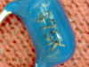
| ❏ | U07 | ADM +DB Double-balanced Mixer | ADE
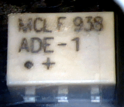 | SMT Mixer | | | RF Front End |
| ❏ | C37 | 0.1 uF | (smt) black stripe
 | SMT 1206 | | | RF Front End |
| ❏ | C39 | 0.1 uF | (smt) black stripe
| SMT 1206 | | | RF Front End |
| ❏ | C41 | 0.1 uF | (smt) black stripe
| SMT 1206 | | | RF Front End |
| ❏ | C42 | 0.1 uF | (smt) black stripe
| SMT 1206 | | | RF Front End |
| ❏ | C38 | 0.01 uF | (smt)
 | SMT 1206 | | | RF Front End |
| ❏ | C40 | 0.01 uF | (smt)
| SMT 1206 | | | RF Front End |
Band Specific Items for 6m Band
| Check | Designation | Component | Marking | Category | Orientation | Notes | Circuit |
|---|
| ❏ | C07 | trimmer capacitor 30 pF | green
| Trimmer | | | RF Front End |
| ❏ | C11 | 2.7 pF | 2.7J | Ceramic | | | RF Front End |
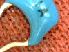
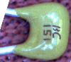
| ❏ | C13 | 150 pF 5% | 151 (may be blue or tan)
 | Ceramic | | (may be blue colored) | RF Front End |
| ❏ | C15 | 180 pF 5% | 181
 | Ceramic | | | RF Front End |
| ❏ | C16 | 220 pF 5% | 221
 | Ceramic | | | RF Front End |
| ❏ | L01 | 0.35uH 11T #26 on T25-6(yellow) (7") | yellow
 | Coil | | | RF Front End |
| ❏ | L01_core | T25-6 toroid core | yellow
| Toroid | | | RF Front End |
| ❏ | L02 | 0.35uH 11T #26 on T25-6(yellow) (7") | yellow
| Coil | | | RF Front End |
| ❏ | L02_core | T25-6 toroid core | yellow
| Toroid | | | RF Front End |
| ❏ | L03 | 0.35uH 11T #26 on T25-6(yellow) (7") | yellow
| Coil | | | RF Front End |
| ❏ | L03_core | T25-6 toroid core | yellow
| Toroid | | | RF Front End |
| ❏ | L04 | 0.78 uH 17T #30 on T25-6 (yellow) (8") | yellow
| Coil | | | RF Front End |
| ❏ | L04_core | T25-6 toroid core | yellow
| Toroid | | | RF Front End |
| ❏ | T02 | 0.53 uH 14T/2x7 bifilar #30 on T25-6(yellow) (8") | yellow
| Xfrmr | | | RF Front End |
| ❏ | T02-core | T25-6 toroid core | yellow
| Toroid | | | RF Front End |
Band Specific Items for 4m Band
| Check | Designation | Component | Marking | Category | Orientation | Notes | Circuit |
|---|
| ❏ | C07 | trimmer capacitor 30 pF | green
| Trimmer | | | RF Front End |
| ❏ | C11 | 2.2 pF | 2.2 | Ceramic | | | RF Front End |
| ❏ | C13 | 120 pF 5% | 121 | Ceramic | | | RF Front End |
| ❏ | C15 | 82 pF | 82J
 | Ceramic | | | RF Front End |
| ❏ | C16 | 270 pF 5% | 271 | Ceramic | | | RF Front End |
| ❏ | L01 | 0.25 uH 9T #26 on T30-6 (yellow) (6") | yellow
| Coil | | | RF Front End |
| ❏ | L01_core | T25-6 toroid core | yellow
| Toroid | | | RF Front End |
| ❏ | L02 | 0.25 uH 9T #26 on T30-6 (yellow) (6") | yellow
| Coil | | | RF Front End |
| ❏ | L02_core | T25-6 toroid core | yellow
| Toroid | | | RF Front End |
| ❏ | L03 | 0.25 uH 9T #26 on T30-6 (yellow) (6") | yellow
| Coil | | | RF Front End |
| ❏ | L03_core | T25-6 toroid core | yellow
| Toroid | | | RF Front End |
| ❏ | L04 | 0.53 uH 14T #30 on T25-6 (10") | yellow
| Coil | | | RF Front End |
| ❏ | L04_core | T25-6 toroid core | yellow
| Toroid | | | RF Front End |
| ❏ | T02 | 0.13uH 7T/2x4 bifilar #30 on T25-6(yellow) (6") | yellow
| Xfrmr | | | RF Front End |
| ❏ | T02-core | T25-6 toroid core | yellow
| Toroid | | | RF Front End |
Band Specific Items for 2m Band
| Check | Designation | Component | Marking | Category | Orientation | Notes | Circuit |
|---|
| ❏ | C07 | trimmer capacitor 10 pF | white
 | Trimmer | | | RF Front End |
| ❏ | C11 | 1.2 pF | 1A
 | Ceramic | | | RF Front End |
| ❏ | C13 | 100 pF 5% | 101
 | Ceramic | | | RF Front End |
| ❏ | C15 | 82 pF | 82J
| Ceramic | | | RF Front End |
| ❏ | C16 | 270 pF 5% | 271 | Ceramic | | | RF Front End |
| ❏ | L01 | 0.08uH 6T #26 on T25-12(green) (5") | green
 | Coil | | | RF Front End |
| ❏ | L01_core | T25-12 toroid core | green
| Toroid | | | RF Front End |
| ❏ | L02 | 0.06 5T #26 on T25-12(green) (4") | green
| Coil | | | RF Front End |
| ❏ | L02_core | T25-12 toroid core | green
| Toroid | | | RF Front End |
| ❏ | L03 | 0.06 5T #26 on T25-12(green) (4") | green
| Coil | | | RF Front End |
| ❏ | L03_core | T25-12 toroid core | green
| Toroid | | | RF Front End |
| ❏ | L04 | 0.53 uH 14T #30 on T25-6 (10") | yellow
| Coil | | | RF Front End |
| ❏ | L04_core | T25-6 toroid core | yellow
| Toroid | | | RF Front End |
| ❏ | T02 | 0.13uH 7T/2x4 bifilar #30 on T25-6(yellow) (6") | yellow
| Xfrmr | | | RF Front End |
| ❏ | T02-core | T25-6 toroid core | yellow
| Toroid | | | RF Front End |
RF Front End Summary Build Notes
- Install FET PreAmp Transistor (Q1)
- Install SMT Capacitors
- Install the Double-Balanced Mixer (U7)
- Wind and Install the Coils (L1-L4)
- Wind and Install T2
- Continuity Test the Inductors
- Install Ceramic Capacitors
- Install Trimmer Capacitors
- Install Diode and Resistors
- Install Antenna Jack (J4)
- Test the Stage
RF Front End Detailed Build Notes
Bottom of the Board
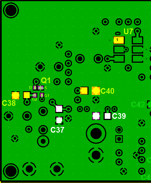
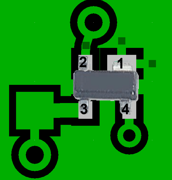
Install FET PreAmp Transistor (Q1)
Install SMT Capacitors
Watch out! There are two types of SMT caps required for this step. The 0.01 µF caps are in the clear strips and shown as yellow in the graphic; the 0.1 µF caps are in the strips with the black strips and are shown using white markings on the graphic.
| Check | Designation | Component | Marking | Category | Orientation | Notes |
|---|
| ❏ | C37 | 0.1 uF | (smt) black stripe
| SMT 1206 | | |
| ❏ | C39 | 0.1 uF | (smt) black stripe
| SMT 1206 | | |
| ❏ | C41 | 0.1 uF | (smt) black stripe
| SMT 1206 | | |
| ❏ | C42 | 0.1 uF | (smt) black stripe
| SMT 1206 | | |
| ❏ | C38 | 0.01 uF | (smt)
| SMT 1206 | | |
| ❏ | C40 | 0.01 uF | (smt)
| SMT 1206 | | |
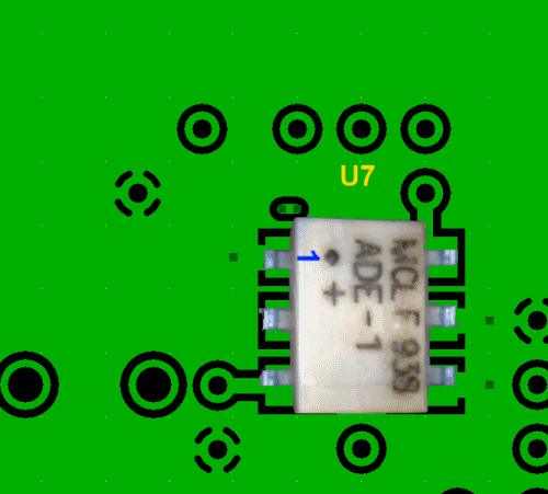
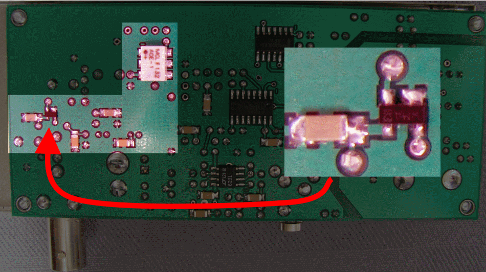
Install the Double-Balanced Mixer (U7)
Top of the Board
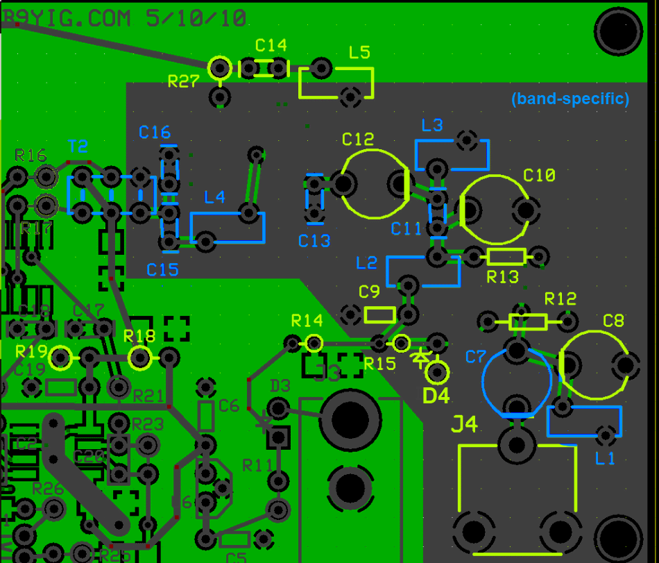
Wind and Install the Coils (L1-L4)
If you are unfamiliar with winding and installing inductors, you may want to refer to the WB5RVZ construction hints for coils (toroidal) and transformers ( toroidal and binocular). Click here for details on identifying toroid cores.
Decoding the trqansformer specifications:
Transformers' windings are specified using the pattern "nnT/wXmmT" or "wXmmT/nnT", where:
- "nn" is the number of turns in the single winding
- "mm" is the number of turns in the multiple windings
- "w" = the number of multiple windings (e.g., 2 = bifilar; 3 = trifilar, etc.)
Thus, e.g., "18T/2x9T bifilar #30" means, using #30 wire, produce a single 18 turn primary winding and two 9-turn secondary windings; "2x9T bifilar/ 18T #30" means, using #30 wire, produce two 9-turn primary windings and a single 18 turn secondary winding.
| Check | Designation | Component | Marking | Category | Orientation | Notes |
|---|
| ❏ | L01 | band-specific |
| Band | Component | Marking |
|---|
| 6m | 0.35uH 11T #26 on T25-6(yellow) (7") (Coil) | yellow |
| 4m | 0.25 uH 9T #26 on T30-6 (yellow) (6") (Coil) | yellow |
| 2m | 0.08uH 6T #26 on T25-12(green) (5") (Coil) | green |
| misc | | |
| ❏ | L01_core | band-specific | | misc | | |
| ❏ | L02 | band-specific |
| Band | Component | Marking |
|---|
| 6m | 0.35uH 11T #26 on T25-6(yellow) (7") (Coil) | yellow |
| 4m | 0.25 uH 9T #26 on T30-6 (yellow) (6") (Coil) | yellow |
| 2m | 0.06 5T #26 on T25-12(green) (4") (Coil) | green |
| misc | | |
| ❏ | L02_core | band-specific | | misc | | |
| ❏ | L03 | band-specific |
| Band | Component | Marking |
|---|
| 6m | 0.35uH 11T #26 on T25-6(yellow) (7") (Coil) | yellow |
| 4m | 0.25 uH 9T #26 on T30-6 (yellow) (6") (Coil) | yellow |
| 2m | 0.06 5T #26 on T25-12(green) (4") (Coil) | green |
| misc | | |
| ❏ | L03_core | band-specific | | misc | | |
| ❏ | L04 | band-specific |
| Band | Component | Marking |
|---|
| 6m | 0.78 uH 17T #30 on T25-6 (yellow) (8") (Coil) | yellow |
| 4m | 0.53 uH 14T #30 on T25-6 (10") (Coil) | yellow |
| 2m | 0.53 uH 14T #30 on T25-6 (10") (Coil) | yellow |
| misc | | |
| ❏ | L04_core | band-specific | | misc | | |
| ❏ | L05 | unused inductor | | Coil | | |
| ❏ | L05_core | unused inductor | | Coil | | |
| ❏ | Magwire26_31in | Magnetic Wire, enameled #26 | | Magnetic | | |
| ❏ | magwire30_40in | Magnetic Wire, enameled #30 | | Magnetic | | |
Wind and Install T2
If you are unfamiliar with winding and installing inductors, you may want to refer to the WB5RVZ construction hints for coils (toroidal) and transformers ( toroidal and binocular). Click here for details on identifying toroid cores.
Decoding the trqansformer specifications:
Transformers' windings are specified using the pattern "nnT/wXmmT" or "wXmmT/nnT", where:
- "nn" is the number of turns in the single winding
- "mm" is the number of turns in the multiple windings
- "w" = the number of multiple windings (e.g., 2 = bifilar; 3 = trifilar, etc.)
Thus, e.g., "18T/2x9T bifilar #30" means, using #30 wire, produce a single 18 turn primary winding and two 9-turn secondary windings; "2x9T bifilar/ 18T #30" means, using #30 wire, produce two 9-turn primary windings and a single 18 turn secondary winding.
| Check | Designation | Component | Marking | Category | Orientation | Notes |
|---|
| ❏ | T02 | band-specific |
| Band | Component | Marking |
|---|
| 6m | 0.53 uH 14T/2x7 bifilar #30 on T25-6(yellow) (8") (Xfrmr) | yellow |
| 4m | 0.13uH 7T/2x4 bifilar #30 on T25-6(yellow) (6") (Xfrmr) | yellow |
| 2m | 0.13uH 7T/2x4 bifilar #30 on T25-6(yellow) (6") (Xfrmr) | yellow |
| misc | | |
| ❏ | T02-core | band-specific | | misc | | |
Continuity Test the Inductors
Using your ohmmeter, test the installed coil and transformer windings by probing the test points with the matching letters:
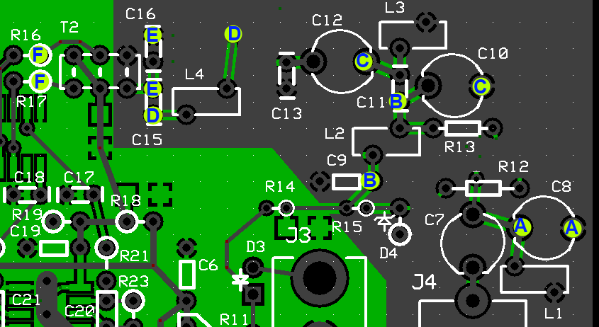
| Test Points | UOM | Nominal Result | Your Result |
|---|
| "A" - "A" (L1) | Continuity | YES | _______ |
| "B" - "B" (L2) | Continuity | YES | _______ |
| "C" - "C" (L3) | Continuity | YES | _______ |
| "D" - "D" (L4) | Continuity | YES | _______ |
| "E" - "E" (T2 - primary) | Continuity | YES | _______ |
| "F" - "F" (T2 Secondaries) | Continuity | YES | _______ |
Install Trimmer Capacitors
Pay careful attention to the orientation of the trimmer capacitors. Align the squared-off side with the corresponding straight line on the silk-screen.
| Check | Designation | Component | Marking | Category | Orientation | Notes |
|---|
| ❏ | C07 | band-specific |
| Band | Component | Marking |
|---|
| 6m | trimmer capacitor 30 pF (Trimmer) | green |
| 4m | trimmer capacitor 30 pF (Trimmer) | green |
| 2m | trimmer capacitor 10 pF (Trimmer) | white |
| misc | | |
| ❏ | C08 | trimmer capacitor 30 pF | green
| Trimmer | | |
| ❏ | C10 | trimmer capacitor 30 pF | green
| Trimmer | | |
| ❏ | C12 | trimmer capacitor 30 pF | green
| Trimmer | | |
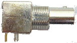
Install Diode and Resistors
Mount D4 hairpin style. The lead at the cathode (banded) end of D4 should be a hairpin lead.
Note: on some earlier boards, R27 was marked as R14 (R27 is next to C14 on the board). The real R14 is between R15 and T2. R27 is up toward the top of the board, underneath the date.
| Check | Designation | Component | Marking | Category | Orientation | Notes |
|---|
| ❏ | D04 | 1N5227B | 1N5227B | Axial | | |
| ❏ | R13 | 33 1/6W 5% | ora-ora-blk-gld
| 1/6W | | |
| ❏ | R27 | 47 1/6W 5% | yel-vio-blk-gld
| 1/6W | | |
| ❏ | R14 | 120 1/6W 5% | brn-red-brn-gld
| 1/6W | | |
| ❏ | R15 | 2.2k 1/6W 5% | red-red-red-gld
| 1/6W | | |
| ❏ | R18 | 2.2k 1/6W 5% | red-red-red-gld
| 1/6W | | |
| ❏ | R19 | 2.2k 1/6W 5% | red-red-red-gld
| 1/6W | | |
| ❏ | R12 | 10 k 1/6W 5% | brn-blk-ora-gld
| 1/6W | | |
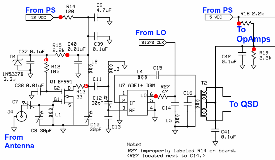
Install Antenna Jack (J4)
| Check | Designation | Component | Marking | Category | Orientation | Notes |
|---|
| ❏ | J04 | BNC Connector Male - PCB mount |
| Jack | | |
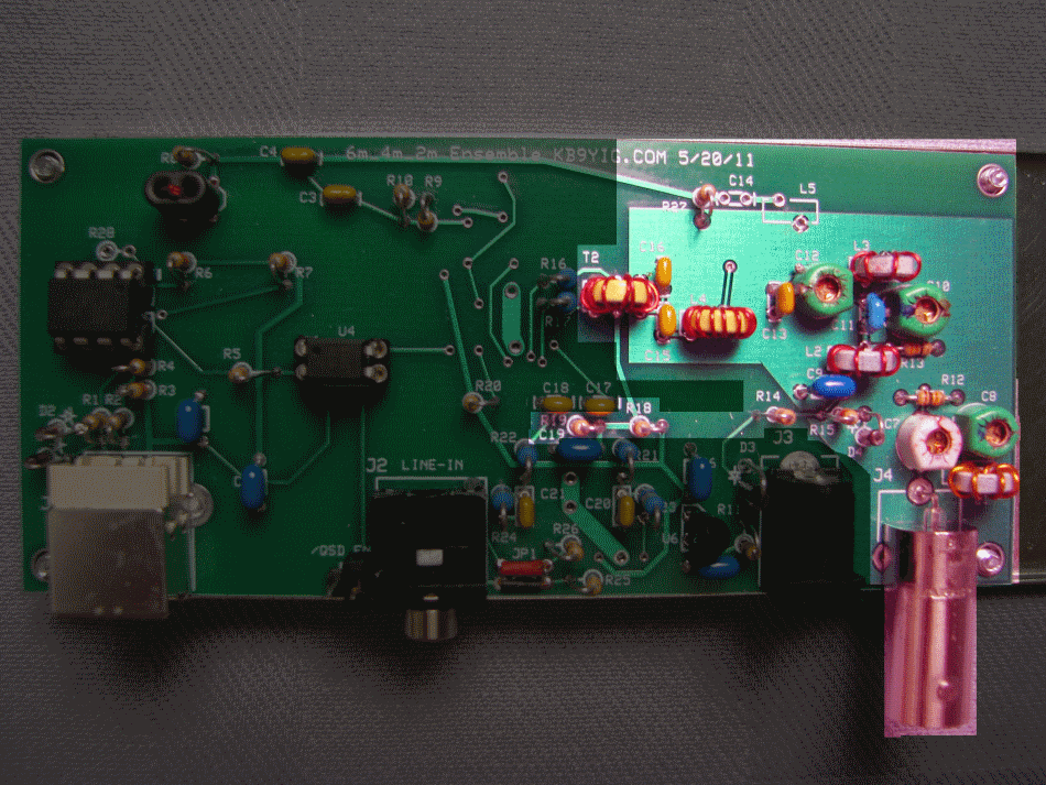
RF Front End Completed Stage
Top of the Board
Bottom of the Board
RF Front End Testing
Current Draw
Test Setup
Power up the board and connect the board to the PC's USB port
Measure the current draw
Test Measurements
| Testpoint | Units | Nominal Value | Author's | Yours |
|---|
| Current Draw | mA | < tbd | tbd | _______ |
Voltage Tests
Test Setup
Power up the board and connect the board to the PC's USB port
Measure the voltages at the testpoints below (all WRT regular ground (use the "/QSD EN" shunt wire for Gnd))
If the voltage at R19 is not around half the 5V rail, the next stage (QSD) will not work. Look at the R18/R19 voltage divider as the likely culprit.
Test Measurements
| Testpoint | Units | Nominal Value | Author's | Yours |
|---|
| R14 hairpin | V dc | 12 | | _______ |
| R18 hairpin | V dc | 5 | | _______ |
| R19 hairpin | V dc | 2.5 | | _______ |
| R12 left-hand lead | V dc | 3.3 | | _______ |