External Connections Introduction
General
Recommended Enclosure
Tom KM5KH offers a very nice enclosure for the Ensemble RX line.
(go directly to build notes)External Connections Schematic
(Resistor testpoints (hairpin, top, or left-hand lead), as physically installed on the board, are marked in the schematic with red dots)

(above schematic has clickable areas that can be used for navigation)
(go directly to build notes)External Connections Bill of Materials
Stage Bill of Materials
(resistor images and color codes courtesy of WIlfried, DL5SWB's R-Color Code program)
| Check | Designation | Component | Marking | Category | Orientation | Notes | Circuit |
|---|---|---|---|---|---|---|---|
| ❏ | Ant | VHF Antenna | User-Supplied | External Connections | |||
| ❏ | Cbl3 | 1/8" M-M Stereo Audio Shld Cable | User-Supplied | External Connections | |||
| ❏ | Cbl4 | Antenna Cable w/BNC | User-Supplied | External Connections |
External Connections Summary Build Notes
- Connect Cables
- Verify Installation of Required Software
- Configure Software
- Test the Stage
External Connections Detailed Build Notes
Top of the Board

Connect Cables
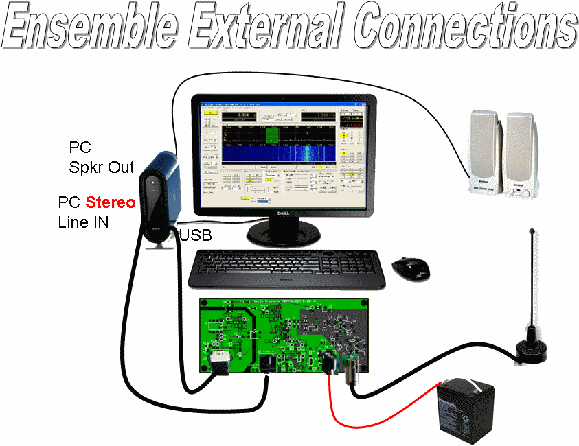
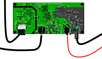
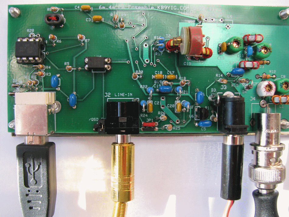
Connect the cables and external components to the receiver:
- J3: 12V Power (ideally to a 12V gel cell or battery vs. Power Supply)
- J1: USB (to the PC)
- J2: Shielded Stereo cable (male-to-male 1/8" plugs) to the Stereo Line-In input of the PC
- J4: Antenna cable of VHF Antenna cia BNC connector
| Check | Designation | Component | Marking | Category | Orientation | Notes |
|---|---|---|---|---|---|---|
| ❏ | Ant | VHF Antenna | User-Supplied | |||
| ❏ | Cbl3 | 1/8" M-M Stereo Audio Shld Cable | User-Supplied | |||
| ❏ | Cbl4 | Antenna Cable w/BNC | User-Supplied |
Verify Installation of Required Software
Review the procedures for software installation to ensure you have obtained and installed all of the requisite software.
Configure Software
In this step, you will configure the Local Oscillator settings, using CFGSR and then configure one of the two recommended SDR programs (Rocky or WinradHD).
CFGSR
See the extremely helpful guide to configuring CFGSR provided by Alan, G4ZFQ.
CFGSR now allows you to specify the rig you want to use with the Si570, and then configures it accordingly.

See PE0FKO's site for further details on use of CFGSR.
External Connections Completed Stage
Top of the Board

External Connections Testing
Test With Rocky
Test Setup
Thanks to Bob G8VOI for much of the info contained in this section.
When it comes to doing the final test and aligning the Ensemble RX, the easiest program to use would be Rocky, as it is possible to edit the Rocky.ini file and put in the appropriate center frequencies for 50.xxxx, 70.xxxx or 144.xxxxMHz directly in it.
Set up Rocky
- Download, unzip, and install Rocky software from Rocky Website
- Edit/replace the Rocky.INI file with entries for desired center frequencies. Sample entry for one center frequency of 146.52 MHz:
146.52MHz=146520000
The following table shows what occurs "behind the curtain" when you set up the Rocky.ini file for a center frequency of 146.52MHz. If you have previously programmed the 0.8 multiplier into the AVR in the above steps, then everything happens automatically:
Event Result Units (1.) Rocky.ini file entry "146.520_MHz=146520000" (2.) Causes Rocky Spectrum Center Freq Display as 146.520 MHz (3.) Rocky Multiplies the Center Frequency by 4 and Sends to AVR 586,080,000 Hz (4.) AVR "undoes" the divide by 4, multiplies the result by .8 and Sends to Si570 117,216,000 Hz (5.) Si570 Oscillates at 117,216,000 Hz (6.) Dividers Produce 29,304,000 Hz (7.) RF Stage Receives Antenna Signal on 146,540,000 Hz (8.) RF Stage's Double-Balanced Mixer Produces IF of 29,324,000 Hz (9.) Ensemble's Mixer Produces baseband IF of 20,000 Hz (10.) Rocky Displays Received signal at 146.540 MHz (You may wish to review the Theory of Operation section on the home page to see graphically what happens "behind the curtains".
Connect Your RX To the External World
Connect up the Ensemble RX II (VHF) board to the PC (antenna, audio, 12V power, and USB cables). Start up Rocky and select a frequency.
Set Up Signal Source
The ideal situation is to use a signal generator to produce a stable signal source to carry out the alignment with, but failing that it can be done with an off air signal such as a beacon or repeater. Using the signal source, tune it to a frequency either side of the selected center frequency.
Sometimes stages like the RF amplifier Q1 can go unstable if it sees a 'strange' load on it's input, so it is good practice to use a 50 ohm attenuator on the input during alignment to ensure it 'sees' a good resistive load, something like 3 or 6dB pad is sufficient. Of course in real life attached to an aerial, conditions will change and the input trimmers might require a slight tweak if there are signs of instability.
Adjust Trimmer Caps
Using Rocky, and a known signal, alignment is simply a case of going through the 4 trimmer capacitors in turn (C7, C8, C10, C12) from the input and adjusting for maximum signal. You will also see a smooth increase in the noise floor level as it is optimised. The temptation is to tune for 'maximum smoke', but those are often the conditions which lead to instability, and therefore it's wiser to back things off a fraction to ensure reliable operation. In practice the small loss of performance sacrificed is not noticeable.