Power Supply Introduction
General
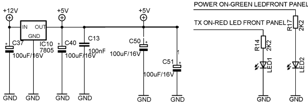
The purpose of this stage is to provide the 5 Volt power rail for the CMOS ICs (as well as provide for Power and TX LEDs and the 12 Volt input point. Make sure your external power supply has the correct volatge (12-13.8 Vdc) and it should be capable of producing 2 to 3 Amps. A faulty or underrated power supply is a very common problem.
See also the GenesisRadio On-Line Pictorials - Phase 1
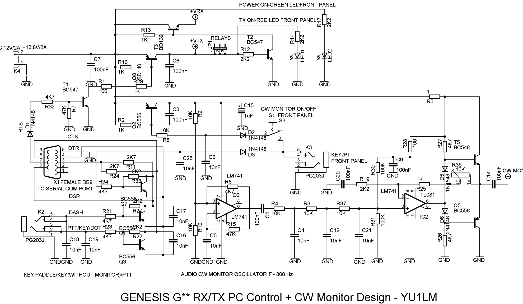
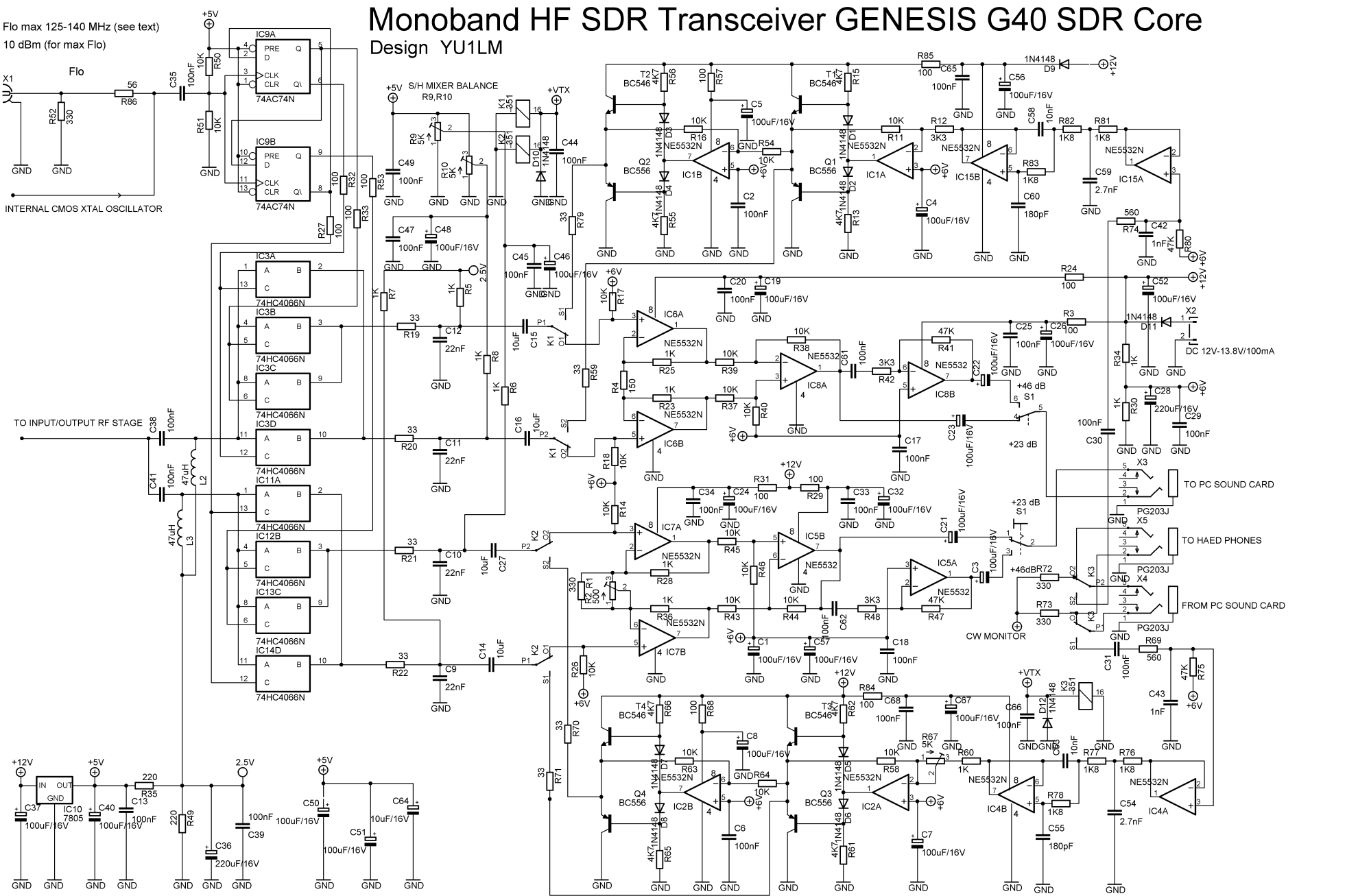
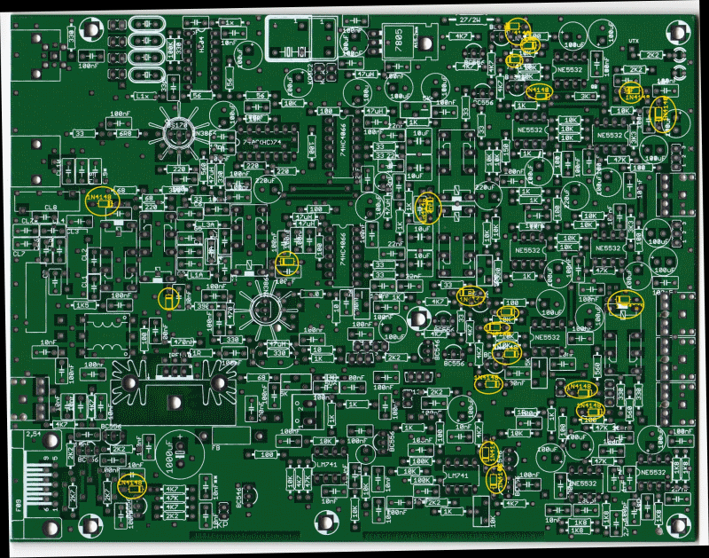
This stage had two areas of the board which were populated to provide the 5 V power supply and the LEDs for RX and TX. In addition, there were some diodes that were populated throughout the board (1 zener and 21 regular diodes). Parts of this stage are spread across two of the schematics: "Genesis G** RX/TX PC Control + CW Monitor Design" and "Monoband HF SDR Transceiver Genesis G40".
Power Supply Schematic
Power Supply Bill of Materials
Stage Bill of Materials
(resistor images and color codes courtesy of WIlfried, DL5SWB's R-Color Code program)
| Check | Count | Component | Marking | Category | Orientation | Notes | Circuit |
|---|---|---|---|---|---|---|---|
| ❏ | 2 | 2k2 1/4W 1% (2.2K) | red-red-blk-brn-brn
 | 1/4W | Power Supply | ||
| ❏ | 1 | 20 2W 1% | red-blk-blk-gld-brn | 2W | Power Supply | ||
| ❏ | 21 | 1N4148 | 1N4148 | Axial | Power Supply | ||
| ❏ | 1 | 1N4734 5V6 Zener Diode | 1N4734 | Axial | Power Supply | ||
| ❏ | 4 | 100 nF | 104
 | ceramic | Power Supply | ||
| ❏ | 2 | 47 uH molded inductor | yel-vio-blk-gld
 | choke | Power Supply | ||
| ❏ | 4 | 100 uF/25Vdc |
 | Electrolytic | Power Supply | ||
| ❏ | 1 | G40 Printed Circuit Board | G40 | Power Supply | |||
| ❏ | 1 | green LED |
 | LED | Power Supply | ||
| ❏ | 1 | red LED |
 | LED | Power Supply | ||
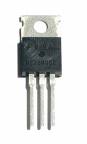
| ❏ | 1 | 78L05 voltage regulator | 78L05
 | TO-220 | Power Supply |
Power Supply Summary Build Notes
- Install Components for 5 V rail
- Install All Diodes to the PCB
- Install Zener Diode
- Test the Stage
Power Supply Detailed Build Notes
Top of the Board
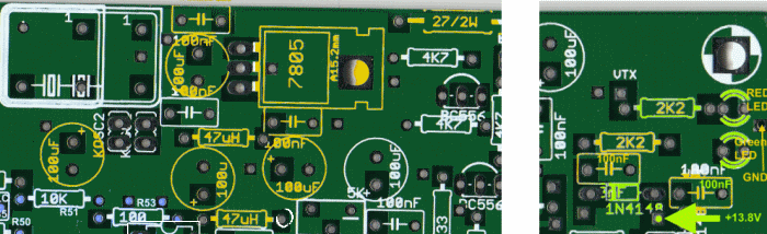
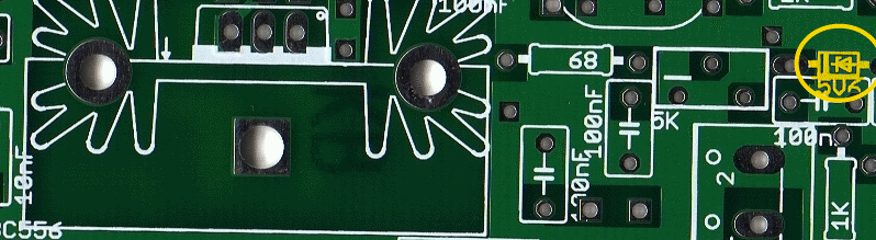
Install Components for 5 V rail
Install all of the components, as per the graphic above.
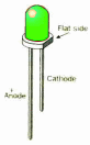
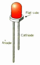
Note: the LEDs are mounted such that their flat (cathode) side is facing toward the right-hand edge of the board (where the board is oriented such that the "WWW.GenesisRadio.com.au " label can be read normally at the bottom)..
| Check | Designation | Component | Marking | Category | Orientation | Notes |
|---|---|---|---|---|---|---|
| ❏ | B1 | G40 Printed Circuit Board | G40 | |||
| ❏ | E138 | 100 nF | 104
| ceramic | ||
| ❏ | E152 | 100 nF | 104
| ceramic | ||
| ❏ | E3 | 100 nF | 104
| ceramic | ||
| ❏ | E88 | 100 nF | 104
| ceramic | ||
| ❏ | E111 | 100 uF/25Vdc |
| Electrolytic | ||
| ❏ | E28 | 100 uF/25Vdc |
| Electrolytic | ||
| ❏ | E39 | 100 uF/25Vdc |
| Electrolytic | ||
| ❏ | E4 | 100 uF/25Vdc |
| Electrolytic | ||
| ❏ | E1 | 78L05 voltage regulator | 78L05
| TO-220 | Take ESD precautions | |
| ❏ | L4 | 47 uH molded inductor | yel-vio-blk-gld
| choke | ||
| ❏ | R16 | 47 uH molded inductor | yel-vio-blk-gld
| choke | ||
| ❏ | R284 | 20 2W 1% | red-blk-blk-gld-brn | 2W | ||
| ❏ | R73 | 2k2 1/4W 1% (2.2K) | red-red-blk-brn-brn
| 1/4W | ||
| ❏ | R74 | 2k2 1/4W 1% (2.2K) | red-red-blk-brn-brn
| 1/4W | ||
| ❏ | E298 | green LED |
| LED | ||
| ❏ | E340 | red LED |
| LED |
Install All Diodes to the PCB
The 21 diodes and their placement were, to borrow a phrase, "all over the board" - literally:
(All these 1N4148 diodes are not really a part of Power Supply unit. There is no functional reason to have them installed in this very first step. The reason is purely a practical one. to basically get rid of them as soon as possible while the PCB is not populated with taller components. Also due to the 'difficult to read' silk screen/print, it was thought that this would be an easy component to miss completely or to install incorrectly. Consequently, just grin and bear it!
Take great care to align the diode's black band with the corresponding band on the silkscreen.
| Check | Designation | Component | Marking | Category | Orientation | Notes |
|---|---|---|---|---|---|---|
| ❏ | E125 | 1N4148 | 1N4148 | Axial | ||
| ❏ | E14 | 1N4148 | 1N4148 | Axial | ||
| ❏ | E175 | 1N4148 | 1N4148 | Axial | ||
| ❏ | E208 | 1N4148 | 1N4148 | Axial | ||
| ❏ | E209 | 1N4148 | 1N4148 | Axial | ||
| ❏ | E226 | 1N4148 | 1N4148 | Axial | ||
| ❏ | E263 | 1N4148 | 1N4148 | Axial | ||
| ❏ | E269 | 1N4148 | 1N4148 | Axial | ||
| ❏ | E324 | 1N4148 | 1N4148 | Axial | ||
| ❏ | E325 | 1N4148 | 1N4148 | Axial | ||
| ❏ | E34 | 1N4148 | 1N4148 | Axial | ||
| ❏ | E341 | 1N4148 | 1N4148 | Axial | ||
| ❏ | E37 | 1N4148 | 1N4148 | Axial | ||
| ❏ | E38 | 1N4148 | 1N4148 | Axial | ||
| ❏ | E41 | 1N4148 | 1N4148 | Axial | ||
| ❏ | E42 | 1N4148 | 1N4148 | Axial | ||
| ❏ | E51 | 1N4148 | 1N4148 | Axial | ||
| ❏ | E52 | 1N4148 | 1N4148 | Axial | ||
| ❏ | E53 | 1N4148 | 1N4148 | Axial | ||
| ❏ | E54 | 1N4148 | 1N4148 | Axial | ||
| ❏ | E253 | 1N4148 | 1N4148 | Axial |
Install Zener Diode
Install the single zener diode as per graphic below. Again, this is not purely a Power Supply requirement, but rather a case of expediency.
| Check | Designation | Component | Marking | Category | Orientation | Notes |
|---|---|---|---|---|---|---|
| ❏ | E242 | 1N4734 5V6 Zener Diode | 1N4734 | Axial |
Power Supply Testing
Power Supply Test
Test Setup
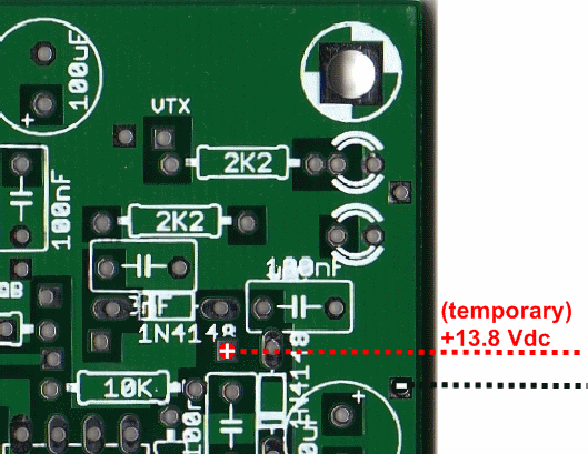
Install temporary power leads at the points indicated in the graphic
- Measure the resistance on the power leads to be sure there is no short. You should see a very high (> 1MEGOhm) resistance
- Temporarily connect the power leads to a +12V to +14V power supply The green LED should light up.
- Measure the voltage on the 5V rail (pin 3 of LM7805) with respect to ground. You should see something on the order of 4.9-5.0 Vdc.
Note: the temporary 12V poweer leads will be used up through the end of phase 6 (original G40 project's Phase 4)
Test Measurements
| Testpoint | Units | Nominal Value | Author's | Yours |
|---|---|---|---|---|
| Power leads | MEGOhm | > 1 | 1.9 | _______ |
| Pin 3 (bottom pin) of Voltage Regulator | Vdc | 5 | 5.02 | _______ |
| Green LED | Lit | Yes | Yes | _______ |