CW Monitor Introduction
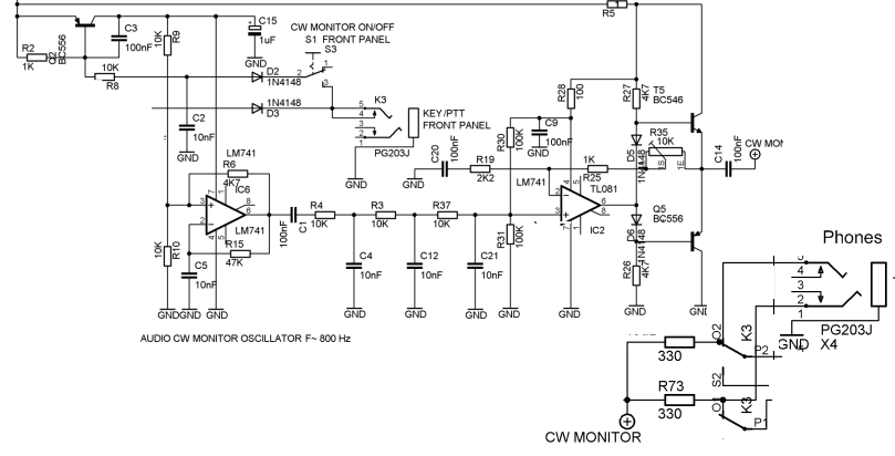
CW Monitor Schematic
CW Monitor Bill of Materials
Stage Bill of Materials
(resistor images and color codes courtesy of WIlfried, DL5SWB's R-Color Code program)
| Check | Count | Component | Marking | Category | Orientation | Notes | Circuit |
|---|---|---|---|---|---|---|---|
| ❏ | 2 | 1 k 1/4W 1% | br-blk-blk-br-br
 | 1/4W | CW Monitor | ||
| ❏ | 6 | 10 k 1/4W 1% | br-blk-blk-r-br
 | 1/4W | CW Monitor | ||
| ❏ | 1 | 100 1/4W 1% | br-blk-blk-blk-br
 | 1/4W | CW Monitor | ||
| ❏ | 2 | 100k 1/4W 1% | brn-blk-blk-orng-brn
 | 1/4W | CW Monitor | ||
| ❏ | 1 | 1R 1/4W 1% (1R) | brn-blk-blk-silver-brn
 | 1/4W | CW Monitor | ||
| ❏ | 1 | 2k2 1/4W 1% (2.2K) | red-red-blk-brn-brn
 | 1/4W | CW Monitor | ||
| ❏ | 2 | 330 1/4W 1% | ora-ora-blk-blk-brn
 | 1/4W | CW Monitor | ||
| ❏ | 1 | 47K 1/4W 1% | yel-vio-blk-red-brn
 | 1/4W | CW Monitor | ||
| ❏ | 3 | 4K7 1/4W 1% (4.7K) | yel-vio-blk-brn-brn
 | 1/4W | CW Monitor | ||
| ❏ | 1 | JRC27F/012 relay | JRC27F/012 | 12V relay | Relay JRC27F/012 12V | CW Monitor | |
| ❏ | 5 | 10 nF (.01uF) | 103
 | Ceramic | CW Monitor | ||
| ❏ | 9 | 100 nF | 104
 | ceramic | CW Monitor | ||
| ❏ | 2 | LM741 OpAmp | LM741 | DIP-8 | CW Monitor | ||
| ❏ | 1 | DPDT Switch | DPDT | S4 CW/SSB/Digimode Switch | CW Monitor | ||
| ❏ | 1 | 1 uF/25Vdc |
 | Electrolytic | CW Monitor | ||
| ❏ | 1 | 100 uF/25Vdc |
 | Electrolytic | CW Monitor | ||
| ❏ | 3 | 3.5mm stereo jack - PCB mount | jack | CW Monitor | |||
| ❏ | 1 | misc hookup wire | misc | CW Monitor | |||
| ❏ | 1 | BC546 NPN Transistor |
 | TO-92 | CW Monitor | ||
| ❏ | 2 | BC556 PNP Transistor |
 | TO-92 | CW Monitor | ||
| ❏ | 1 | 10K (Y103) | Y103 | trimpot | CW Monitor |
CW Monitor Summary Build Notes
- Install Resistors
- Install Capacitors
- Install Connectors and Active Components
- Install Wires and Switches
- Test the Stage
CW Monitor Detailed Build Notes
Top of the Board
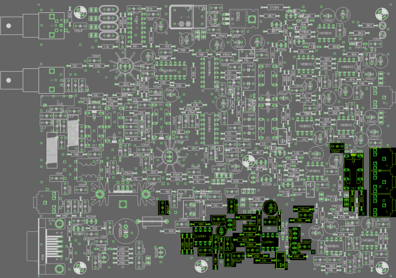
Install Resistors
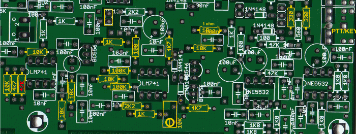
| Check | Designation | Component | Marking | Category | Orientation | Notes |
|---|---|---|---|---|---|---|
| ❏ | R76 | 1R 1/4W 1% (1R) | brn-blk-blk-silver-brn
 | 1/4W | ||
| ❏ | R54 | 100 1/4W 1% | br-blk-blk-blk-br
 | 1/4W | ||
| ❏ | R40 | 100k 1/4W 1% | brn-blk-blk-orng-brn
 | 1/4W | ||
| ❏ | R41 | 100k 1/4W 1% | brn-blk-blk-orng-brn
 | 1/4W | ||
| ❏ | R6 | 330 1/4W 1% | ora-ora-blk-blk-brn
 | 1/4W | ||
| ❏ | R7 | 330 1/4W 1% | ora-ora-blk-blk-brn
 | 1/4W | ||
| ❏ | R31 | 1 k 1/4W 1% | br-blk-blk-br-br
 | 1/4W | ||
| ❏ | R43 | 1 k 1/4W 1% | br-blk-blk-br-br
 | 1/4W | ||
| ❏ | R42 | 2k2 1/4W 1% (2.2K) | red-red-blk-brn-brn
 | 1/4W | ||
| ❏ | R56 | 4K7 1/4W 1% (4.7K) | yel-vio-blk-brn-brn
 | 1/4W | ||
| ❏ | R30 | 10 k 1/4W 1% | br-blk-blk-r-br
 | 1/4W | ||
| ❏ | R33 | 10 k 1/4W 1% | br-blk-blk-r-br
 | 1/4W | ||
| ❏ | R36 | 10 k 1/4W 1% | br-blk-blk-r-br
 | 1/4W | ||
| ❏ | R38 | 10 k 1/4W 1% | br-blk-blk-r-br
 | 1/4W | ||
| ❏ | R66 | 10 k 1/4W 1% | br-blk-blk-r-br
 | 1/4W | ||
| ❏ | R77 | 10 k 1/4W 1% | br-blk-blk-r-br
 | 1/4W | ||
| ❏ | R35 | 4K7 1/4W 1% (4.7K) | yel-vio-blk-brn-brn
 | 1/4W | ||
| ❏ | R55 | 4K7 1/4W 1% (4.7K) | yel-vio-blk-brn-brn
 | 1/4W | ||
| ❏ | R34 | 47K 1/4W 1% | yel-vio-blk-red-brn
 | 1/4W | ||
| ❏ | E143 | 10K (Y103) | Y103 | trimpot |
Install Capacitors
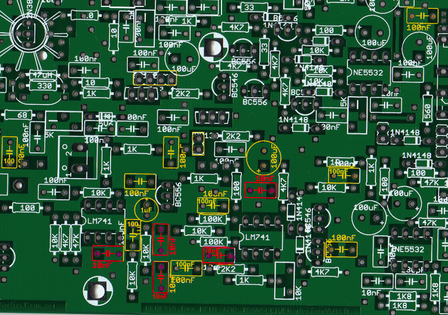
| Check | Designation | Component | Marking | Category | Orientation | Notes |
|---|---|---|---|---|---|---|
| ❏ | E177 | 10 nF (.01uF) | 103
 | Ceramic | ||
| ❏ | E179 | 10 nF (.01uF) | 103
 | Ceramic | ||
| ❏ | E213 | 10 nF (.01uF) | 103
 | Ceramic | ||
| ❏ | E214 | 10 nF (.01uF) | 103
 | Ceramic | ||
| ❏ | E240 | 10 nF (.01uF) | 103
 | Ceramic | ||
| ❏ | E123 | 100 nF | 104
 | ceramic | ||
| ❏ | E176 | 100 nF | 104
 | ceramic | ||
| ❏ | E178 | 100 nF | 104
 | ceramic | ||
| ❏ | E182 | 100 nF | 104
 | ceramic | ||
| ❏ | E19 | 100 nF | 104
 | ceramic | ||
| ❏ | E199 | 100 nF | 104
 | ceramic | ||
| ❏ | E210 | 100 nF | 104
 | ceramic | ||
| ❏ | E55 | 100 nF | 104
 | ceramic | ||
| ❏ | E60 | 100 nF | 104
 | ceramic | ||
| ❏ | E128 | 1 uF/25Vdc |
 | Electrolytic | ||
| ❏ | E81 | 100 uF/25Vdc |
 | Electrolytic |
Install Connectors and Active Components
Solder the remaining components for Phase 5. Pay attention to the locations of BC556 and BC546 transistors and the alignment/orientation of the OpAmps IC uA741!
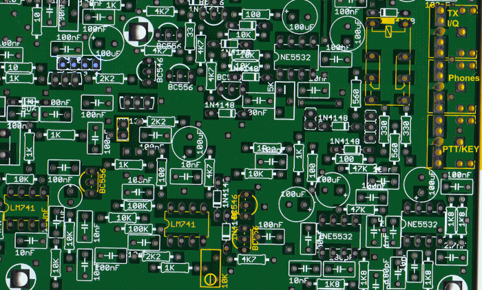
| Check | Designation | Component | Marking | Category | Orientation | Notes |
|---|---|---|---|---|---|---|
| ❏ | E11 | 3.5mm stereo jack - PCB mount | jack | |||
| ❏ | E15 | 3.5mm stereo jack - PCB mount | jack | |||
| ❏ | E8 | 3.5mm stereo jack - PCB mount | jack | |||
| ❏ | E184 | LM741 OpAmp | LM741 | DIP-8 | Take ESD precautions | |
| ❏ | E59 | LM741 OpAmp | LM741 | DIP-8 | Take ESD precautions | |
| ❏ | E13 | JRC27F/012 relay | JRC27F/012 | 12V relay | Relay JRC27F/012 12V | |
| ❏ | E185 | BC546 NPN Transistor |
 | TO-92 | ||
| ❏ | E131 | BC556 PNP Transistor |
 | TO-92 | ||
| ❏ | E262 | BC556 PNP Transistor |
 | TO-92 |
Install Wires and Switches
Install Three Temporary Wires
Install the three temporary wires, presented as dotted lines in the graphic. These can be installed on either the topside or the underside of the board, according to the builder's preference.
- Provide DC power to this circuit. This can be accomplished in two ways:
- Remove the previously installed temporary Vin and GND wires from the upper right-hand corner of the board. And install temporary connections (+12-13.8v dc power lines (+Vin and GND) as shown in the diagram;
- Alternatively, leave the existing Vcc connection (in the upper left-hand corner of the board) and connect the positive side of that connection to the point indicated on the graphic, "jumpering" the +12Vdc to the CW Monitor circuit (e.g., with a clip lead)
- Install connector wire to patch CW Monitor audio
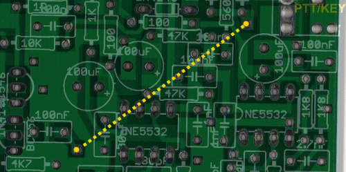
Install S4 - CW/SSB/Digimode Switch
Using an SPST (or DPDT acting as SPST) switch, connect the switch and wires as shown in the graphic. (S4 is represented variously on in the G40 docs as S3; switch designations were reworked to adjust for the duplication of S1 in earlier phases)
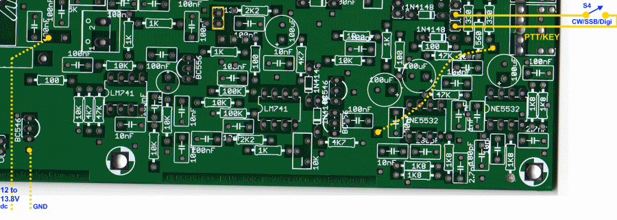
| Check | Designation | Component | Marking | Category | Orientation | Notes |
|---|---|---|---|---|---|---|
| ❏ | S4 | DPDT Switch | DPDT | S4 CW/SSB/Digimode Switch | ||
| ❏ | wire4 | misc hookup wire | misc |
CW Monitor Testing
CW Monitor Test
Test Setup
- Plug in headphones and CW key
- Connect power (either via newly added temporary wires or via existing Vcc connection and jumper wire)
-
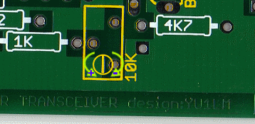
Adjust the CW sidetone volume with the trimmer Y103 (10K) while holding the key down.
- Turning the trimmer clockwise REDUCES volume
- Turning the trimmer counter-clockwise INCREASES the volume.
