RX RF In Introduction
General
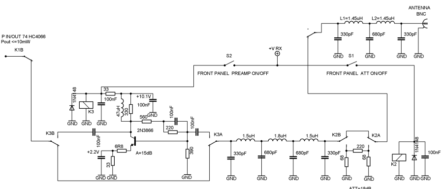
In this phase, we complete the permanent path for the RF between the S/H detectors/modulators, removing the temporary wire path installed in the preceding phase. The permanent path includes the low-pass and band-pass filters, and the relay (K1) that switches the RF path from its default RX configuration to the TX configuration.
Relay K1 is powered from the Vtx bus. activated via the PTT control signals. The Vtx will be provided in the finished board via a wire, connecting the K1 coil to the Vtx bus via. This wire is designated the "C-C" wire in the final wiring diagram.
We also add switch-selectable RF attenuation (17dB) and switch-selectable RF pre-amplification (15dB) circuitry, with the relays (K2 and K3) that switch these circuits in and out of the path. The relays K2 and K3 are powered from the Vrx bus, when it is switched to the relays via switches S2 and S3 (the schematic designates them as S1 and S2).
RX RF In Schematic
RX RF In Bill of Materials
Stage Bill of Materials
(resistor images and color codes courtesy of WIlfried, DL5SWB's R-Color Code program)
| Check | Count | Component | Marking | Category | Orientation | Notes | Circuit |
|---|---|---|---|---|---|---|---|
| ❏ | 1 | Magnet wire, enameled #20 | 28" (70 cm) for the pair of coils | RX RF In | |||
| ❏ | 1 | 1K5 (1.5k) 1/4W 1% | brn-grn-blk-brn-brn
 | 1/4W | RX RF In | ||
| ❏ | 2 | 220 1/4W 1% | red-red-blk-blk-brn
 | 1/4W | RX RF In | ||
| ❏ | 2 | 33 1/4W 1% | ora-ora-blk-gld-brn
 | 1/4W | RX RF In | ||
| ❏ | 1 | 330 1/4W 1% | ora-ora-blk-blk-brn
 | 1/4W | RX RF In | ||
| ❏ | 1 | 390 1/4W 1% | ora-whi-blk-blk-brn
 | 1/4W | RX RF In | ||
| ❏ | 1 | 560 1/4W 1% | grn-blu-blk-blk-brn
 | 1/4W | RX RF In | ||
| ❏ | 2 | 68 1/4W 1% | blu-gry-blk-gld-brn
 | 1/4W | RX RF In | ||
| ❏ | 1 | 6R8 1/4W 1% (6.8) | blu-gry-blk-silver-brn
 | 1/4W | RX RF In | ||
| ❏ | 3 | JRC27F/012 relay | JRC27F/012 | 12V relay | Relay JRC27F/012 12V | RX RF In | |
| ❏ | 1 | 1.5 uH molded inductor |
 | axial | "L1A" on pcb | RX RF In | |
| ❏ | 1 | 1.5 uH molded inductor |
 | axial | "L3A" on pcb | RX RF In | |
| ❏ | 1 | 1.8 uH molded inductor |
 | axial | "L2A" on pcb | RX RF In | |
| ❏ | 9 | 100 nF | 104
 | ceramic | RX RF In | ||
| ❏ | 1 | 330 pF | 331 | Ceramic | "C2" on pcb | RX RF In | |
| ❏ | 1 | 330 pF | 331 | Ceramic | "C6" on pcb | RX RF In | |
| ❏ | 1 | 330 pF | 331 | Ceramic | "CL1" on pcb | RX RF In | |
| ❏ | 1 | 330 pF | 331 | Ceramic | "CL9" on pcb | RX RF In | |
| ❏ | 1 | 680 pF | 681 | Ceramic | "C3" on pcb | RX RF In | |
| ❏ | 1 | 680 pF | 681 | Ceramic | "C5" on pcb | RX RF In | |
| ❏ | 1 | 680 pF | 681 | Ceramic | "CL7*" on pcb | RX RF In | |
| ❏ | 1 | 47 uH molded inductor | yel-vio-blk-gld
 | choke | RX RF In | ||
| ❏ | 1 | DPDT Switch | DPDT | S2 RX Attenuator Off/On | RX RF In | ||
| ❏ | 1 | DPDT Switch | DPDT | S3 RX Pre-Amp On/Off switch | RX RF In | ||
| ❏ | 1 | 0 pF | jumper | jumper wire - "C1" on pcb | RX RF In | ||
| ❏ | 1 | 0 pF | jumper | jumper wire - "C7" on pcb | RX RF In | ||
| ❏ | 1 | 0 pF | jumper | jumper wire - "CL10" on pcb | RX RF In | ||
| ❏ | 1 | 0 pF | jumper | jumper wire between top holes of CL6 and CL5 - "CL6" on pcb | RX RF In | ||
| ❏ | 1 | misc hookup wire | misc | RX RF In | |||
| ❏ | 1 | TO-39 heatsink |
 | misc | RX RF In | ||
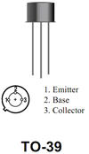
| ❏ | 1 | 2N3866 NPN Transistor |
 | TO-39 | RX RF In | ||
| ❏ | 1 | T50-2 | red | toroid | L1 toroidal coil (17T (14") #20) | RX RF In | |
| ❏ | 1 | T50-2 | red | toroid | L2 toroidal coil (17T (14") #20) | RX RF In |
RX RF In Summary Build Notes
- Remove Temporary Wire
- Install Passive Components
- Install Antenna Switching Relays
- Install PreAmp Transistor
- Wind and Install LPF Toroids
- Install Underside Jumper Wire
- Temporarily Install SW2 and SW3
- Test the Stage
RX RF In Detailed Build Notes
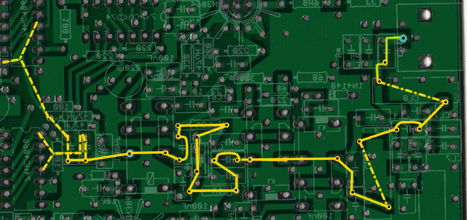
Bottom of the Board
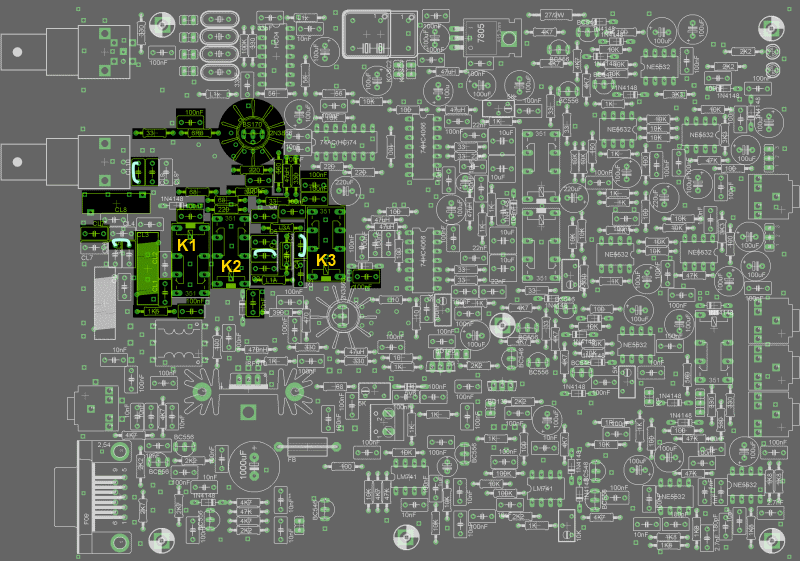
Top of the Board
Install Passive Components
Install resistors, capacitors, chokes, and jumpers
When installing the jumpers, allow the jumper to clear the board by a quarter of an inch (~6mm) to allow for testing
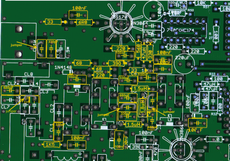
| Check | Designation | Component | Marking | Category | Orientation | Notes |
|---|---|---|---|---|---|---|
| ❏ | R58 | 6R8 1/4W 1% (6.8) | blu-gry-blk-silver-brn
 | 1/4W | ||
| ❏ | R59 | 33 1/4W 1% | ora-ora-blk-gld-brn
 | 1/4W | ||
| ❏ | R99 | 33 1/4W 1% | ora-ora-blk-gld-brn
 | 1/4W | ||
| ❏ | R37 | 68 1/4W 1% | blu-gry-blk-gld-brn
 | 1/4W | ||
| ❏ | R75 | 68 1/4W 1% | blu-gry-blk-gld-brn
 | 1/4W | ||
| ❏ | R61 | 220 1/4W 1% | red-red-blk-blk-brn
 | 1/4W | ||
| ❏ | R98 | 220 1/4W 1% | red-red-blk-blk-brn
 | 1/4W | ||
| ❏ | R60 | 330 1/4W 1% | ora-ora-blk-blk-brn
 | 1/4W | ||
| ❏ | R62 | 560 1/4W 1% | grn-blu-blk-blk-brn
 | 1/4W | ||
| ❏ | R63 | 390 1/4W 1% | ora-whi-blk-blk-brn
 | 1/4W | ||
| ❏ | R70 | 1K5 (1.5k) 1/4W 1% | brn-grn-blk-brn-brn
 | 1/4W | ||
| ❏ | E130 | 0 pF | jumper | jumper wire - "C1" on pcb | ||
| ❏ | E193 | 0 pF | jumper | jumper wire - "CL10" on pcb | ||
| ❏ | E320 | 0 pF | jumper | jumper wire between top holes of CL6 and CL5 - "CL6" on pcb | ||
| ❏ | E330 | 0 pF | jumper | jumper wire - "C7" on pcb | ||
| ❏ | E189 | 100 nF | 104
 | ceramic | ||
| ❏ | E192 | 100 nF | 104
 | ceramic | ||
| ❏ | E202 | 100 nF | 104
 | ceramic | ||
| ❏ | E205 | 100 nF | 104
 | ceramic | ||
| ❏ | E223 | 100 nF | 104
 | ceramic | ||
| ❏ | E224 | 100 nF | 104
 | ceramic | ||
| ❏ | E227 | 100 nF | 104
 | ceramic | ||
| ❏ | E79 | 100 nF | 104
 | ceramic | ||
| ❏ | E91 | 100 nF | 104
 | ceramic | ||
| ❏ | E220 | 330 pF | 331 | Ceramic | "C2" on pcb | |
| ❏ | E284 | 330 pF | 331 | Ceramic | "CL9" on pcb | |
| ❏ | E323 | 330 pF | 331 | Ceramic | "CL1" on pcb | |
| ❏ | E329 | 330 pF | 331 | Ceramic | "C6" on pcb | |
| ❏ | E211 | 680 pF | 681 | Ceramic | "C5" on pcb | |
| ❏ | E318 | 680 pF | 681 | Ceramic | "CL7*" on pcb | |
| ❏ | E326 | 680 pF | 681 | Ceramic | "C3" on pcb | |
| ❏ | L2 | 1.5 uH molded inductor |
 | axial | "L1A" on pcb | |
| ❏ | L5 | 1.5 uH molded inductor |
 | axial | "L3A" on pcb | |
| ❏ | E328 | 1.8 uH molded inductor |
 | axial | "L2A" on pcb | |
| ❏ | R57 | 47 uH molded inductor | yel-vio-blk-gld
 | choke |
Install Antenna Switching Relays
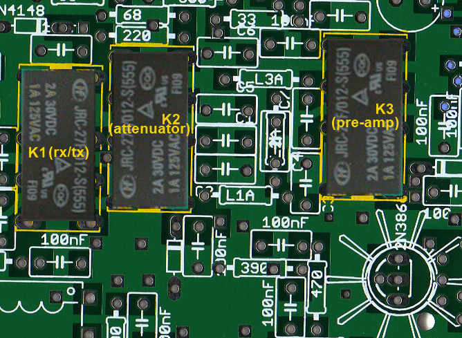
| Check | Designation | Component | Marking | Category | Orientation | Notes |
|---|---|---|---|---|---|---|
| ❏ | E187 | JRC27F/012 relay | JRC27F/012 | 12V relay | Relay JRC27F/012 12V | |
| ❏ | E191 | JRC27F/012 relay | JRC27F/012 | 12V relay | Relay JRC27F/012 12V | |
| ❏ | E217 | JRC27F/012 relay | JRC27F/012 | 12V relay | Relay JRC27F/012 12V |
Install PreAmp Transistor
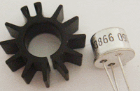
|
NOTE: the heat sink is factory supplied so tight that it would not be possible to place it over the 2N3866 after the transistor is soldered to the PCB. Therefore it is important to insert the 2N3866 into the heat sink first. |
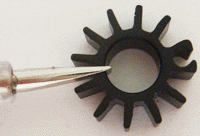
|
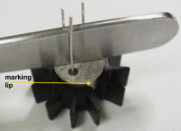
Prepare the heat sink by gently spreading its collar. |
|
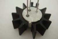
Place the transistor over the heat sink with the marking lip in the middle of the gap, push it down with the flat side of metal tweezers. The grip should be firm and tight (if it is too tight or loose, remove the transistor and adjust the collar) |
|
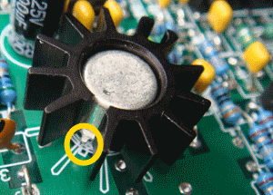
The transistor and its heatsink will resemble this when ready for mounting |
|
Place the 2N3866 into PCB (marking lip alignment as per photo). Solder it approx 4-5 mm (about 3/16") above PCB, just enough to clear any surrounding components. TIP: Initially, solder one lead only. Then adjust for height and level, as needed, and then solder the other two leads. |
| Check | Designation | Component | Marking | Category | Orientation | Notes |
|---|---|---|---|---|---|---|
| ❏ | E87 | TO-39 heatsink |
 | misc | ||
| ❏ | E222 | 2N3866 NPN Transistor |
 | TO-39 |
Wind and Install LPF Toroids
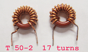
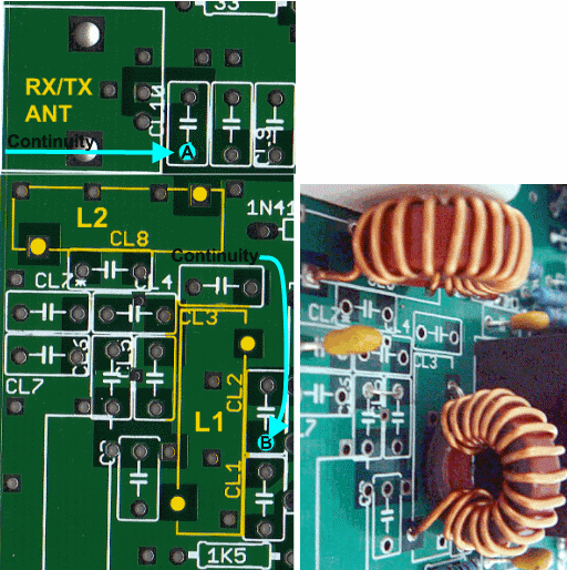
This transceiver requires exactly two wound toroids! L1 and L2 (each 1.45 uH) are each wound on a T50-2 core with 17 turns of 0.8 mm (#20 AWG) wire, exactly as per photo. Make sure to remove enamel coating and tin the leads before mounting. The length of wire required for each coil is about 13-14" (about 35 cm).
| Check | Designation | Component | Marking | Category | Orientation | Notes |
|---|---|---|---|---|---|---|
| ❏ | E194 | T50-2 | red | toroid | L1 toroidal coil (17T (14") #20) | |
| ❏ | E245 | T50-2 | red | toroid | L2 toroidal coil (17T (14") #20) | |
| ❏ | wire2 | Magnet wire, enameled #20 | 28" (70 cm) for the pair of coils |
Install Underside Jumper Wire
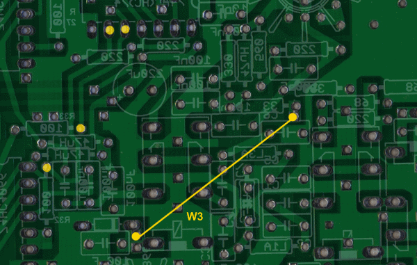
Refer to the "W3" on the topside diagram below.
Insert a "marker" wire lead or a short length of ssolder into the holes at each end of W3 (to identify the holes. Then, turn over the board and install the length of wire that will become W3 on the underside (removing the temporary hole identifying wires as you install each end of W3).
Take care to use a very short end of the wire when inserting into the hole. Do not let the end protrude more than a mm or so on the top side of the board, as it will be extremely difficult to cut off the excess end in the cramped quarters topside.
| Check | Designation | Component | Marking | Category | Orientation | Notes |
|---|---|---|---|---|---|---|
| ❏ | w3 | misc hookup wire | misc |
Temporarily Install SW2 and SW3
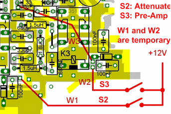
S2 is the Attenuator on/off switch; S3 is the Pre-Amp on/off switch.
Connect the two switches using temporary wires w1 and w2 and a temporary connection to the 12V bus.
If possible, use IC clip leads to avoid soldering and then removing the temporary wires.
These switches will be permanently installed in the PC RX/TX Control Phase (Phase 8)

| Check | Designation | Component | Marking | Category | Orientation | Notes |
|---|---|---|---|---|---|---|
| ❏ | S2 | DPDT Switch | DPDT | S2 RX Attenuator Off/On | ||
| ❏ | S3 | DPDT Switch | DPDT | S3 RX Pre-Amp On/Off switch |
RX RF In Testing
Coils Continuity Test
Test Setup
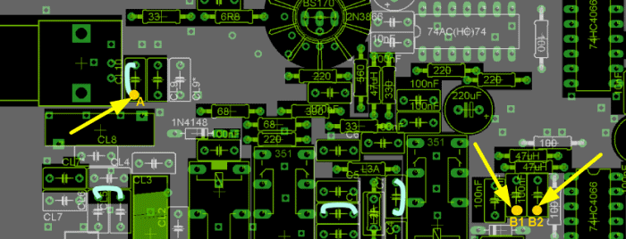
Refer to the graphic showing the three continuity test points "A" and "B1, B2". Using the Ohmmeter, test for continuity between A and B.
If you do not get continuity, then refer to the graphic at the beginning of this phase (depicting an underside view of the rx path from the bnc connector to the mixers). Trace continuity through each point until the break is discovered.
Test Measurements
| Testpoint | Units | Nominal Value | Author's | Yours |
|---|---|---|---|---|
| A (jumper wire) and B1 (bottom lead of 100 nF coupling capacitor) | Ohms | 0 | 1 | _______ |
| A (jumper wire) and B2 (bottom lead of 100 nF coupling capacitor) | Ohms | 0 | 1 | _______ |
Attenuator Test
Test Setup
Test Attenuator and Pre-Amp Operation AttenuatorTo test attenuator preamplifier:
- Power on the board and connect I/Q out to PC's stereo Line-In (or "mic") jack
- Tune the SDR PC program to a 40m signal (or connect a signal generator)
- Observe signal strength
- Turn S2 (attenuator) switch on
- Observe signal strength - signal will decrease for approximately 17dB
Pre-Amplifier Test
Test Setup
With power still on and signal present:
- Turn S2 (attenuator switch OFF
- Observe signal strength
- Turn S3 (pre-amp switch) ON
- Observe signal strength - you should see an improvement of 15dB
Voltage Test
Test Setup
With power on and S3 (Pre-Amp switch) ON:
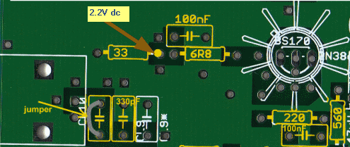
Measure the voltage at the testpoint shown below - should read 2.2V dc (with respect to ground). The testpoint is the junction of the 33 Ohm and 6.8 Ohm resistors at the emitter end of the 2N3866 Pre-Amp transistor.
Test Measurements
| Testpoint | Units | Nominal Value | Author's | Yours |
|---|---|---|---|---|
| Testpoint | V dc | ~2.2 | 2.01 | _______ |
RX Complete
Test Setup
At this point, the receiver has been completed. Now, remove the temporary switches (S2 and S3) and their associated wires, and move on to the transmitter!