TX Sample Hold Modulator Introduction
General
This phase takes two signals (I and Q) from the PC Soundcard and produces four quadrature outputs to the bilateral mixing switches. The process is essentially the reverse of the RX side. Since the mixers are bilateral, the TX signals in quadrature go through the same process of sampling and holding, clocked by the Quadrature signals from the dividers.
TX Sample Hold Modulator Schematic
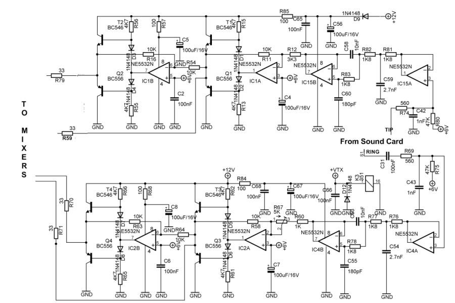
TX Sample Hold Modulator Bill of Materials
Stage Bill of Materials
(resistor images and color codes courtesy of WIlfried, DL5SWB's R-Color Code program)
| Check | Count | Component | Marking | Category | Orientation | Notes | Circuit |
|---|---|---|---|---|---|---|---|
| ❏ | 1 | 1 k 1/4W 1% | br-blk-blk-br-br
 | 1/4W | TX Sample Hold Modulator | ||
| ❏ | 6 | 10 k 1/4W 1% | br-blk-blk-r-br
 | 1/4W | TX Sample Hold Modulator | ||
| ❏ | 4 | 100 1/4W 1% | br-blk-blk-blk-br
 | 1/4W | TX Sample Hold Modulator | ||
| ❏ | 6 | 1K8 (1.8k) 1/4W 1% | brn-gry-blk-brn-brn
 | 1/4W | TX Sample Hold Modulator | ||
| ❏ | 3 | 33 1/4W 1% | ora-ora-blk-gld-brn
 | 1/4W | TX Sample Hold Modulator | ||
| ❏ | 1 | 3k3 1/4W 1% (3.3K) | ora-ora-blk-brn-brn
 | 1/4W | TX Sample Hold Modulator | ||
| ❏ | 2 | 47K 1/4W 1% | yel-vio-blk-red-brn
 | 1/4W | TX Sample Hold Modulator | ||
| ❏ | 8 | 4K7 1/4W 1% (4.7K) | yel-vio-blk-brn-brn
 | 1/4W | TX Sample Hold Modulator | ||
| ❏ | 2 | 560 1/4W 1% | grn-blu-blk-blk-brn
 | 1/4W | TX Sample Hold Modulator | ||
| ❏ | 2 | 1 nF USM | 102J
 | Ceramic | shown in graphic as 102J | TX Sample Hold Modulator | |
| ❏ | 1 | 10 nF (.01uF) | 103
 | Ceramic | TX Sample Hold Modulator | ||
| ❏ | 2 | 10 nF USM | 103J
 | Ceramic | shown in graphic as 103J | TX Sample Hold Modulator | |
| ❏ | 5 | 100 nF | 104
 | ceramic | TX Sample Hold Modulator | ||
| ❏ | 2 | 100 nF USM | 104J
 | Ceramic | shown in graphic as 104J | TX Sample Hold Modulator | |
| ❏ | 2 | 180 pF USM | 181K
 | Ceramic | shown in graphic as 181K | TX Sample Hold Modulator | |
| ❏ | 2 | 2.7 nF USM | 272J
 | Ceramic | shown in graphic as 272J | TX Sample Hold Modulator | |
| ❏ | 4 | NE5532 Dual OpAmp |
 | DIP-8 | TX Sample Hold Modulator | ||
| ❏ | 7 | 100 uF/25Vdc |
 | Electrolytic | TX Sample Hold Modulator | ||
| ❏ | 2 | misc hookup wire | misc | TX Sample Hold Modulator | |||
| ❏ | 4 | BC546 NPN Transistor |
 | TO-92 | TX Sample Hold Modulator | ||
| ❏ | 4 | BC556 PNP Transistor |
 | TO-92 | TX Sample Hold Modulator | ||
| ❏ | 1 | 5K (Y502) | Y502
 | trimpot | Needs to be initialized. Before installing this trimmer, adjust the resistance between the middle pin and either of the other pins to 2.5 K Ohm. | TX Sample Hold Modulator |
TX Sample Hold Modulator Summary Build Notes
- Uninstall CW Monitor Temporary Wire
- Install Bottom Right Components
- Install Upper Right Components
- Install Mid-Right Components
- Adjust Trimmer
- Reinstall CW Monitor Wire (from Phase 5)
- Install Permanent Wires
- Test the Stage
TX Sample Hold Modulator Detailed Build Notes
Top of the Board
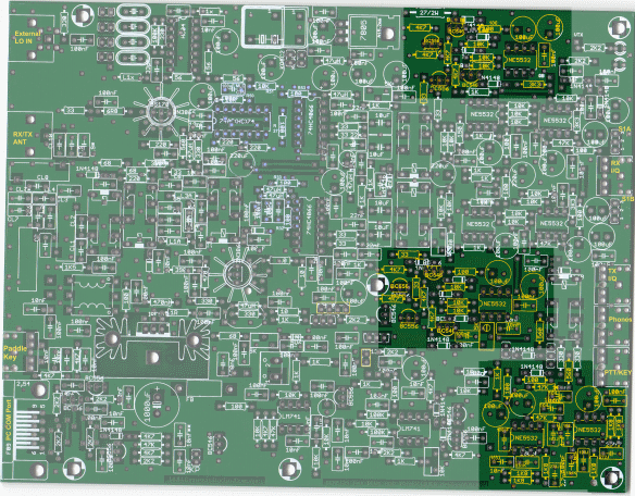
Uninstall CW Monitor Temporary Wire
Find the temporary wire placed during Phase 7 to enable CW Monitoring and uninstall it so as tp provide room for installing components in this phase.
This wire will be re-installed to the bottom of the board at the end of this phase.
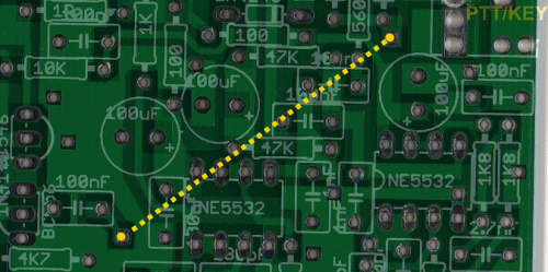
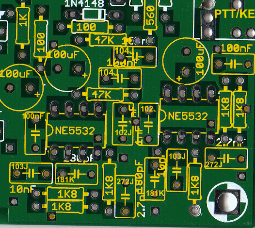
Install Bottom Right Components
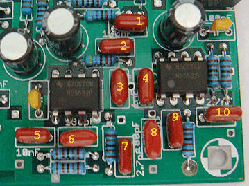
USM capacitors chart:

1. 100nF [ 104J]
2. 100nF [ 104J]
3. 1 nF [ 102J]
4. 1 nF [ 102J]
5. 10 nF [ 103J]
6. 180 pF [181K]
7. 2.7 nF [272J]
8. 180 pF [181K]
9. 10 nF [ 103J]
10. 2.7 nF [272J]
| Check | Designation | Component | Marking | Category | Orientation | Notes |
|---|---|---|---|---|---|---|
| ❏ | E283 | 180 pF USM | 181K
 | Ceramic | shown in graphic as 181K | |
| ❏ | E300 | 180 pF USM | 181K
 | Ceramic | shown in graphic as 181K | |
| ❏ | E288 | 1 nF USM | 102J
 | Ceramic | shown in graphic as 102J | |
| ❏ | E294 | 1 nF USM | 102J
 | Ceramic | shown in graphic as 102J | |
| ❏ | E293 | 2.7 nF USM | 272J
 | Ceramic | shown in graphic as 272J | |
| ❏ | E299 | 2.7 nF USM | 272J
 | Ceramic | shown in graphic as 272J | |
| ❏ | E291 | 10 nF USM | 103J
 | Ceramic | shown in graphic as 103J | |
| ❏ | E297 | 10 nF USM | 103J
 | Ceramic | shown in graphic as 103J | |
| ❏ | E286 | 100 nF | 104
 | ceramic | ||
| ❏ | E287 | 100 nF | 104
 | ceramic | ||
| ❏ | E289 | 100 nF USM | 104J
 | Ceramic | shown in graphic as 104J | |
| ❏ | E290 | 100 nF USM | 104J
 | Ceramic | shown in graphic as 104J | |
| ❏ | E278 | 100 uF/25Vdc |
 | Electrolytic | ||
| ❏ | E279 | 100 uF/25Vdc |
 | Electrolytic | ||
| ❏ | E292 | 100 uF/25Vdc |
 | Electrolytic | ||
| ❏ | R45 | 100 1/4W 1% | br-blk-blk-blk-br
 | 1/4W | ||
| ❏ | R78 | 100 1/4W 1% | br-blk-blk-blk-br
 | 1/4W | ||
| ❏ | R5 | 560 1/4W 1% | grn-blu-blk-blk-brn
 | 1/4W | ||
| ❏ | R22 | 1 k 1/4W 1% | br-blk-blk-br-br
 | 1/4W | ||
| ❏ | R82 | 1K8 (1.8k) 1/4W 1% | brn-gry-blk-brn-brn
 | 1/4W | ||
| ❏ | R83 | 1K8 (1.8k) 1/4W 1% | brn-gry-blk-brn-brn
 | 1/4W | ||
| ❏ | R84 | 1K8 (1.8k) 1/4W 1% | brn-gry-blk-brn-brn
 | 1/4W | ||
| ❏ | R85 | 1K8 (1.8k) 1/4W 1% | brn-gry-blk-brn-brn
 | 1/4W | ||
| ❏ | R86 | 1K8 (1.8k) 1/4W 1% | brn-gry-blk-brn-brn
 | 1/4W | ||
| ❏ | R87 | 1K8 (1.8k) 1/4W 1% | brn-gry-blk-brn-brn
 | 1/4W | ||
| ❏ | R79 | 47K 1/4W 1% | yel-vio-blk-red-brn
 | 1/4W | ||
| ❏ | R81 | 47K 1/4W 1% | yel-vio-blk-red-brn
 | 1/4W | ||
| ❏ | E188 | NE5532 Dual OpAmp |
 | DIP-8 | Take ESD precautions | |
| ❏ | E285 | NE5532 Dual OpAmp |
 | DIP-8 | Take ESD precautions |
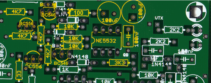
Install Upper Right Components
Install components as indicated in graphic
| Check | Designation | Component | Marking | Category | Orientation | Notes |
|---|---|---|---|---|---|---|
| ❏ | E254 | 100 nF | 104
 | ceramic | ||
| ❏ | E27 | 100 uF/25Vdc |
 | Electrolytic | ||
| ❏ | E98 | 100 uF/25Vdc |
 | Electrolytic | ||
| ❏ | E29 | 33 1/4W 1% | ora-ora-blk-gld-brn
 | 1/4W | ||
| ❏ | R13 | 100 1/4W 1% | br-blk-blk-blk-br
 | 1/4W | ||
| ❏ | R67 | 3k3 1/4W 1% (3.3K) | ora-ora-blk-brn-brn
 | 1/4W | ||
| ❏ | R1 | 4K7 1/4W 1% (4.7K) | yel-vio-blk-brn-brn
 | 1/4W | ||
| ❏ | R16 | 4K7 1/4W 1% (4.7K) | yel-vio-blk-brn-brn
 | 1/4W | ||
| ❏ | R18 | 4K7 1/4W 1% (4.7K) | yel-vio-blk-brn-brn
 | 1/4W | ||
| ❏ | R2 | 4K7 1/4W 1% (4.7K) | yel-vio-blk-brn-brn
 | 1/4W | ||
| ❏ | R11 | 10 k 1/4W 1% | br-blk-blk-r-br
 | 1/4W | ||
| ❏ | R17 | 10 k 1/4W 1% | br-blk-blk-r-br
 | 1/4W | ||
| ❏ | R19 | 10 k 1/4W 1% | br-blk-blk-r-br
 | 1/4W | ||
| ❏ | E31 | BC546 NPN Transistor |
 | TO-92 | ||
| ❏ | E32 | BC556 PNP Transistor |
 | TO-92 | ||
| ❏ | E35 | BC546 NPN Transistor |
 | TO-92 | ||
| ❏ | E36 | BC556 PNP Transistor |
 | TO-92 | ||
| ❏ | E33 | NE5532 Dual OpAmp |
 | DIP-8 | Take ESD precautions |
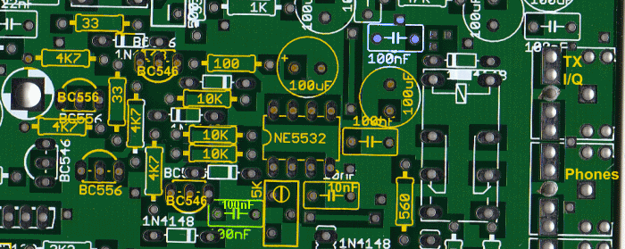
Install Mid-Right Components
| Check | Designation | Component | Marking | Category | Orientation | Notes |
|---|---|---|---|---|---|---|
| ❏ | E46 | NE5532 Dual OpAmp |
 | DIP-8 | Take ESD precautions | |
| ❏ | E56 | 10 nF (.01uF) | 103
 | Ceramic | ||
| ❏ | E338 | 100 nF | 104
 | ceramic | ||
| ❏ | E57 | 100 nF | 104
 | ceramic | ||
| ❏ | E24 | 100 uF/25Vdc |
 | Electrolytic | ||
| ❏ | E45 | 100 uF/25Vdc |
 | Electrolytic | ||
| ❏ | R4 | 33 1/4W 1% | ora-ora-blk-gld-brn
 | 1/4W | ||
| ❏ | R999 | 33 1/4W 1% | ora-ora-blk-gld-brn
 | 1/4W | ||
| ❏ | R21 | 100 1/4W 1% | br-blk-blk-blk-br
 | 1/4W | ||
| ❏ | R80 | 560 1/4W 1% | grn-blu-blk-blk-brn
 | 1/4W | ||
| ❏ | R23 | 4K7 1/4W 1% (4.7K) | yel-vio-blk-brn-brn
 | 1/4W | ||
| ❏ | R25 | 4K7 1/4W 1% (4.7K) | yel-vio-blk-brn-brn
 | 1/4W | ||
| ❏ | R8 | 4K7 1/4W 1% (4.7K) | yel-vio-blk-brn-brn
 | 1/4W | ||
| ❏ | R9 | 4K7 1/4W 1% (4.7K) | yel-vio-blk-brn-brn
 | 1/4W | ||
| ❏ | R20 | 10 k 1/4W 1% | br-blk-blk-r-br
 | 1/4W | ||
| ❏ | R24 | 10 k 1/4W 1% | br-blk-blk-r-br
 | 1/4W | ||
| ❏ | R26 | 10 k 1/4W 1% | br-blk-blk-r-br
 | 1/4W | ||
| ❏ | E47 | BC546 NPN Transistor |
 | TO-92 | ||
| ❏ | E49 | BC546 NPN Transistor |
 | TO-92 | ||
| ❏ | E48 | BC556 PNP Transistor |
 | TO-92 | ||
| ❏ | E50 | BC556 PNP Transistor |
 | TO-92 | ||
| ❏ | E21 | 5K (Y502) | Y502
 | trimpot | Needs to be initialized. Before installing this trimmer, adjust the resistance between the middle pin and either of the other pins to 2.5 K Ohm. |
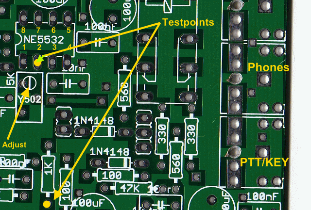
Adjust Trimmer
(With Power OFF): Connect your ohmmeter between the following points : pin 2 of the NE5532 and the 1K resistor. Adjust the trimmer Y502 until the ohmmeter reads 3.3KO
Reinstall CW Monitor Wire (from Phase 5)
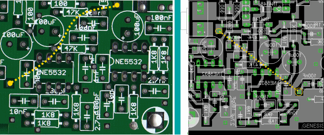
Reinstall W4, the wire placed during Phase 7 to enable CW Monitoring (permanently) on the underside of the board.
Install Permanent Wires
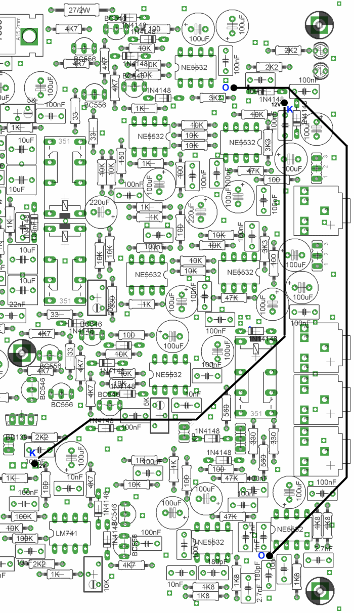
Install permanent wires ("W8" and "W9") per the graphic. Click here for a higher-resolution view of the layout of these wires.
The end-points of the wires are annotated on the graphic:
- W8: endpoints are marked "O"
- W9: endpoints are marked "K"
Hint: use a short length of solder wire or other wire to act as a "marker" for each of the endpoint holes, permitting you to identify the hole for installation on the underside of the board.
| Check | Designation | Component | Marking | Category | Orientation | Notes |
|---|---|---|---|---|---|---|
| ❏ | W8 | misc hookup wire | misc | |||
| ❏ | W9 | misc hookup wire | misc |