PC RXTX Control Introduction
General
This stage is changed for kits whose serial number is greater than 100. The change is discused in this series of messages on the reflector
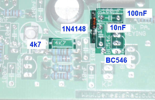
The change introduces extra components to the BOM, as indicated in the labels in the above image. These extra components are not shown in the BOM(s) below.
PC RXTX Control Schematic
PC RXTX Control Bill of Materials
Stage Bill of Materials
(resistor images and color codes courtesy of WIlfried, DL5SWB's R-Color Code program)
| Check | Count | Component | Marking | Category | Orientation | Notes | Circuit |
|---|---|---|---|---|---|---|---|
| ❏ | 2 | 1 k 1/4W 1% | br-blk-blk-br-br
 | 1/4W | PC RXTX Control | ||
| ❏ | 1 | 100 1/4W 1% | br-blk-blk-blk-br
 | 1/4W | PC RXTX Control | ||
| ❏ | 5 | 2k2 1/4W 1% (2.2K) | red-red-blk-brn-brn
 | 1/4W | PC RXTX Control | ||
| ❏ | 2 | 2k7 1/4W 1% (2.7K) | red-vio-blk-brn-brn
 | 1/4W | PC RXTX Control | ||
| ❏ | 1 | 47K 1/4W 1% | yel-vio-blk-red-brn
 | 1/4W | PC RXTX Control | ||
| ❏ | 4 | 4K7 1/4W 1% (4.7K) | yel-vio-blk-brn-brn
 | 1/4W | PC RXTX Control | ||
| ❏ | 1 | Ferrite Bead | axial | PC RXTX Control | |||
| ❏ | 6 | 10 nF (.01uF) | 103
 | Ceramic | PC RXTX Control | ||
| ❏ | 1 | 10 nF** | 103
| Ceramic | PC RXTX Control | ||
| ❏ | 10 | 100 nF | 104
 | ceramic | PC RXTX Control | ||
| ❏ | 1 | 1000 uF/25Vdc |
 | Electrolytic | PC RXTX Control | ||
| ❏ | 1 | db9 connector - PCB mount | jack | PC RXTX Control | |||
| ❏ | 1 | BD139 NPN Transistor |
 | TO-126 | PC RXTX Control | ||
| ❏ | 1 | BD140 PNP Transistor |
| TO-126 | PC RXTX Control | ||
| ❏ | 2 | BC546 NPN Transistor |
| TO-92 | PC RXTX Control | ||
| ❏ | 3 | BC556 PNP Transistor |
| TO-92 | PC RXTX Control | ||
| ❏ | 1 | 5K (Y502) | Y502
 | trimpot | Needs to be initialized. Before installing this trimmer, adjust the resistance between the middle pin and either of the other pins to 2.5 K Ohm. | PC RXTX Control |
PC RXTX Control Summary Build Notes
- Install Capacitors and Resistors
- Install BD139 and BD140 Transistors
- Install the Remainder of the Parts
- Install Permanent Jump Wires and Vin Wires
- Test the Stage
PC RXTX Control Detailed Build Notes
Top of the Board
Install Capacitors and Resistors
Be careful - there are some easily confused values in the resistors (2.2 vs 2.7 k; 4.7k vs 47k, etc.). Note Also the locations of the seven 10nF capacitors vs. the ten 100 nF capacitors
| Check | Designation | Component | Marking | Category | Orientation | Notes |
|---|---|---|---|---|---|---|
| ❏ | R65 | 100 1/4W 1% | br-blk-blk-blk-br
| 1/4W | ||
| ❏ | R39 | 1 k 1/4W 1% | br-blk-blk-br-br
| 1/4W | ||
| ❏ | R88 | 1 k 1/4W 1% | br-blk-blk-br-br
| 1/4W | ||
| ❏ | R27 | 2k2 1/4W 1% (2.2K) | red-red-blk-brn-brn
| 1/4W | ||
| ❏ | R71 | 2k2 1/4W 1% (2.2K) | red-red-blk-brn-brn
| 1/4W | ||
| ❏ | R72 | 2k2 1/4W 1% (2.2K) | red-red-blk-brn-brn
| 1/4W | ||
| ❏ | R91 | 2k2 1/4W 1% (2.2K) | red-red-blk-brn-brn
| 1/4W | ||
| ❏ | R93 | 2k2 1/4W 1% (2.2K) | red-red-blk-brn-brn
| 1/4W | ||
| ❏ | R94 | 2k7 1/4W 1% (2.7K) | red-vio-blk-brn-brn
| 1/4W | ||
| ❏ | R95 | 2k7 1/4W 1% (2.7K) | red-vio-blk-brn-brn
| 1/4W | ||
| ❏ | R10 | 4K7 1/4W 1% (4.7K) | yel-vio-blk-brn-brn
| 1/4W | ||
| ❏ | R29 | 4K7 1/4W 1% (4.7K) | yel-vio-blk-brn-brn
| 1/4W | ||
| ❏ | R89 | 4K7 1/4W 1% (4.7K) | yel-vio-blk-brn-brn
| 1/4W | ||
| ❏ | R90 | 4K7 1/4W 1% (4.7K) | yel-vio-blk-brn-brn
| 1/4W | ||
| ❏ | R28 | 47K 1/4W 1% | yel-vio-blk-red-brn
| 1/4W | ||
| ❏ | E119 | 10 nF (.01uF) | 103
| Ceramic | ||
| ❏ | E150 | 10 nF** | 103
| Ceramic | ||
| ❏ | E16 | 10 nF (.01uF) | 103
| Ceramic | ||
| ❏ | E273 | 10 nF (.01uF) | 103
| Ceramic | ||
| ❏ | E277 | 10 nF (.01uF) | 103
| Ceramic | ||
| ❏ | E306 | 10 nF (.01uF) | 103
| Ceramic | ||
| ❏ | E307 | 10 nF (.01uF) | 103
| Ceramic | ||
| ❏ | E121 | 100 nF | 104
| ceramic | ||
| ❏ | E134 | 100 nF | 104
| ceramic | ||
| ❏ | E183 | 100 nF | 104
| ceramic | ||
| ❏ | E212 | 100 nF | 104
| ceramic | ||
| ❏ | E233 | 100 nF | 104
| ceramic | ||
| ❏ | E243 | 100 nF | 104
| ceramic | ||
| ❏ | E247 | 100 nF | 104
| ceramic | ||
| ❏ | E267 | 100 nF | 104
| ceramic | ||
| ❏ | E282 | 100 nF | 104
| ceramic | ||
| ❏ | E62 | 100 nF | 104
| ceramic | ||
| ❏ | E180 | 1000 uF/25Vdc |
| Electrolytic |
Install BD139 and BD140 Transistors
It's a good idea to test the transistor before installing - some have been reported as having shorts between base and collector.
| Check | Designation | Component | Marking | Category | Orientation | Notes |
|---|---|---|---|---|---|---|
| ❏ | E239 | BD139 NPN Transistor |
| TO-126 | ||
| ❏ | E173 | BD140 PNP Transistor |
| TO-126 |
Install the Remainder of the Parts
BC5x6 Transistors
Install the transistors (note that there are 3 BC556 and 1 BC546.)
Install the Ferrite Bead - see photo
| Check | Designation | Component | Marking | Category | Orientation | Notes |
|---|---|---|---|---|---|---|
| ❏ | E101 | BC546 NPN Transistor |
| TO-92 | ||
| ❏ | E22 | BC546 NPN Transistor |
| TO-92 | ||
| ❏ | E105 | BC556 PNP Transistor |
| TO-92 | ||
| ❏ | E310 | BC556 PNP Transistor |
| TO-92 | ||
| ❏ | E311 | BC556 PNP Transistor |
| TO-92 | ||
| ❏ | E12 | db9 connector - PCB mount | jack | |||
| ❏ | E335 | Ferrite Bead | axial | |||
| ❏ | E238 | 5K (Y502) | Y502
| trimpot | Needs to be initialized. Before installing this trimmer, adjust the resistance between the middle pin and either of the other pins to 2.5 K Ohm. |
Install Permanent Jump Wires and Vin Wires
S2 and S3 from the RF-In Phase
Rewire switches S2 and S3 (from Phase 4) by removing their temporary wiring and
installing permanent wiring as below
(Note: topside and underside views are provided to assist in identifying correct connection points/holes. While it is a builder's choice, it is recommended to install all of these wires on the underside of the board.)w:
Install Permanant Vin Wiring
Disconnect +Vin temporary lines from lower left corner area of the pcb and upper right-hand corner of the PCB.
Install permanent +Vin
PC RXTX Control Testing
Test Step 1
Test Setup
Connect Temporary Switches/Wires SX1 and SX2
In order to test the PC PX/TX Control, we need to temporarily hook up a couple of switches, per the diagram below:
PC RX/TX control testing should be performed in 2 steps. This is step 1:
- Using a DMM, measure the voltage at +VTX. It should be 0V and voltage at +VRX=+12-+13.8V.
- Set switch SX1 ON. When switch SX1 is ON, +VTX will measure +12-13.8V and +VRXwill be 0V.
Test Measurements
| Testpoint | Units | Nominal Value | Author's | Yours |
|---|---|---|---|---|
| SX1 OFF, SX2 OFF - Vtx | V dc | 0 | <1 (mv noise) | _______ |
| SX1 OFF, SX2 OFF - Vrx | V dc | +12 to +13.8 | 11.85 (using 12.26 Vcc) | _______ |
| SX1 ON, SX2 OFF - Vtx | V dc | +12 to +13.8 | 12.13 (using 12.26 Vcc) | _______ |
| SX1 ON, SX2 OFF - Vrx | V dc | 0 | <1 (mv noise) | _______ |
Test Step 2
Test Setup
- Turn SX1 OFF.
- Connect Genesis G40 to the serial PC port directly or via USB/ Serial adapter.
- Settings in SDR software should be set according to the DB9 connector's Pins as shown below:
Sub D9 Pin State Function TX Action 4 DTR Always HIGH Always HIGH 5 GND 6 DSR PTT/KEY ,dot EL KEYER Connect to DTR 7 RTS LOW for RX HIGH for TX 8 CTS Dash EL KEYER Connect to DTR - Turn on SX2 (temporarily installed in Test Step 1) and +VTX should be +12-+13.8V.
NOTE: for more details refer to G40 homepage: PC RX/TX control under PowerSDR and M0KGK.
Test Measurements
| Testpoint | Units | Nominal Value | Author's | Yours |
|---|---|---|---|---|
| SX1 OFF, SX2 ON - Vtx | V dc | +12 to +13.8 | _______ |