USB_Power Supply Introduction
General
This stage is quite simple, sort of an "icebreaker" for the builder. It provides the interface to the computer via a USB cable and provides the +5V dc power via the USB cable to power the digital "side" of the MOBO with 5 vdc and a ground isolated from the analog "side".
It is always a good idea to double check the bill of materials in this set of documentation with the official BOM on the Mobo site. Discrepancies may be introduced inadvertently, as the changes are sometimes not communicated or discovered, making timely update of this site a problem.
Theory of Operation
The MOBO is divided into two "sides", the digital and the analog sides. These two sides are galvanically isolated from one another by two separate ground planes and 5 V voltage sources on the board. The digital side is powered by a USB-provided 5 volt source labeled "+5Vd" against a ground plane labeled "DGND".
The analog side has 12 V power (from the mated Softrock RXTX V6.3) and a regulated 5 volt source derived from that voltage. Voltages and grounds are indicated by the customary labels ("+12V, +5V, GND"). Interaction between the digital and analog "sides" is via an ADUM1251 which bridges the I2C signals across the two sides.
(go directly to build notes)USB_Power Supply Schematic
(Click for Full Schematic)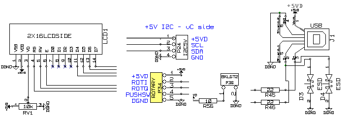
C:\Users\Rob\Documents\HamStuff\SDR\MOBO4_x\mobo43
(go directly to build notes)USB_Power Supply Bill of Materials
Stage Bill of Materials
(resistor images and color codes courtesy of WIlfried, DL5SWB's R-Color Code program)
| Check | Count | Component | Marking | Category |
|---|---|---|---|---|
| ❏ | 1 | header, 14-pin | Header | |
| ❏ | 1 | header, 2-pin |
 | Header |
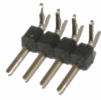
| ❏ | 1 | header, 4-pin RA |
 | Header |
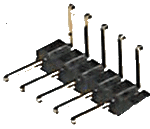
| ❏ | 1 | header, 5-pin RA |
 | Header |
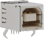
| ❏ | 1 | USB-B pcb jack (rt-angle) |
 | Jack-RA |
| ❏ | 2 | 22 ohm 1% | SMT 0805 1/8W | |
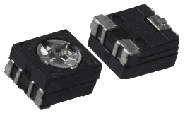
| ❏ | 1 | 10 k ohm pot |
 | SMT 0805 POT |
| ❏ | 1 | 10 ohm 5% | SMT 1206 1/4W | |
| ❏ | 2 | bi-directional 5V SMT diode |
 | Socket |
USB_Power Supply Summary Build Notes
- Mount USB Jack
- Install Bottomside Resistors and Diodes
- Install Digital Headers
- Test the Stage
USB_Power Supply Detailed Build Notes
Bottom of the Board
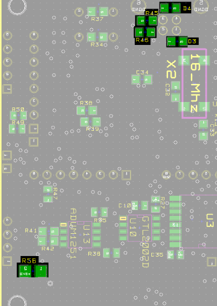
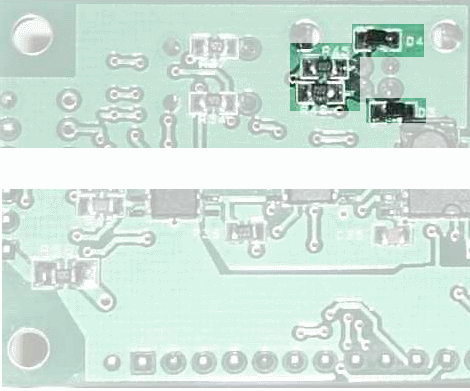
Install Bottomside Resistors and Diodes
| Check | Designation | Component | Marking | Category | Orientation | Notes |
|---|---|---|---|---|---|---|
| ❏ | D03 | bi-directional 5V SMT diode |
 | Socket | bi-directional diodes (no orientation issues) | horiz |
| ❏ | R56 | 10 ohm 5% | SMT 1206 1/4W | horiz | ||
| ❏ | D04 | bi-directional 5V SMT diode |
 | Socket | bi-directional diodes (no orientation issues) | horiz |
| ❏ | R45 | 22 ohm 1% | SMT 0805 1/8W | horiz | ||
| ❏ | R46 | 22 ohm 1% | SMT 0805 1/8W | horiz |
Top of the Board
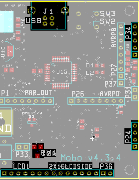
Mount USB Jack
| Check | Designation | Component | Marking | Category | Orientation | Notes |
|---|---|---|---|---|---|---|
| ❏ | J01 | USB-B pcb jack (rt-angle) |
 | Jack-RA |
Install Digital Headers
Graeme ZL2APV advises that, In this step, you should install RV1 first as it is really hard to get the iron tip down to that pot with the plug in place - don't ask :-) Also may note that LCD1 incorporates P36 to bring the total pin count, at the LCD end, up to 16 pins.
All of these headers are installed with the short ends in the solder holes and the long ends protruding out feom the board topside.
A later change to the BOM replaced P34 and P24 straight headers with right-angled headers. This change came AFTER the photos of the completed (BETA) board below. Don't let that confuse you. Right-angled is correct for these headers.
| Check | Designation | Component | Marking | Category | Orientation | Notes |
|---|---|---|---|---|---|---|
| ❏ | VR1 | 10 k ohm pot |
 | SMT 0805 POT | Install BEFORE installing P36 and LCD01 header strips | |
| ❏ | LCD1 | header, 14-pin | Header | |||
| ❏ | P36 | header, 2-pin |
 | Header | LCD background LED light This will mate with Pin 15-16 of SIL LCD connector. Current from USB port | |
| ❏ | P24 | header, 4-pin RA |
 | Header | I2C connector For attaching external uC, such as SDR-Widget board | |
| ❏ | P34 | header, 5-pin RA |
 | Header | Rotary Encoder |
USB_Power Supply Completed Stage
Top of the Board
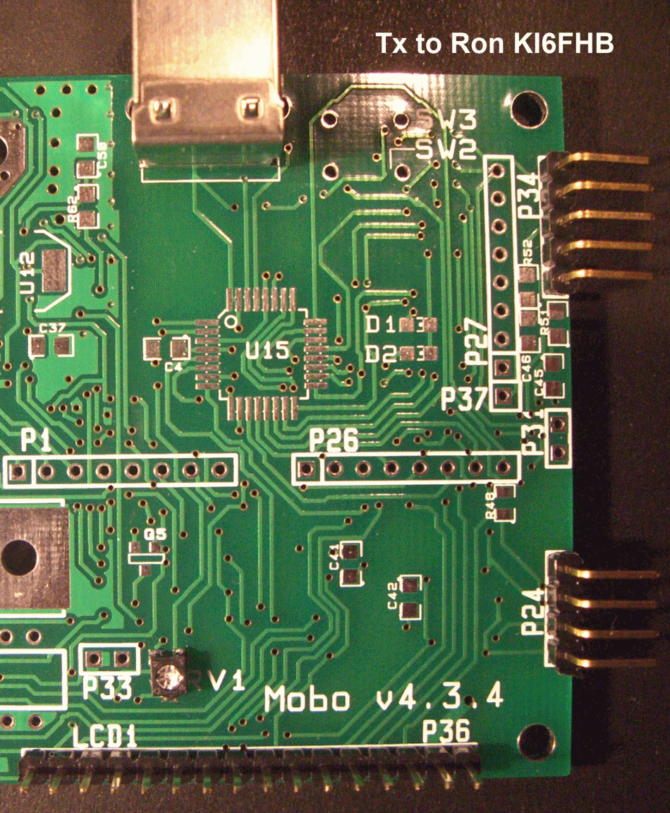
Bottom of the Board
USB_Power Supply Testing
Test for Digital Isolation
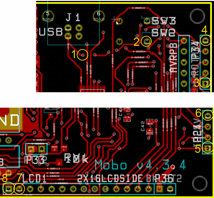
Test Setup
Connect the board's USB jack via a USB cable to a PC's USB connector
measure voltage at the testpoints shown on the graphic
Test Measurements
| Testpoint | Units | Nominal Value | Author's | Yours |
|---|---|---|---|---|
| Point 1 with respect to point 2 | V dc | +5 | tbd | _______ |
| Point 3 with respect to point 4 | V dc | +5 | tbd | _______ |
| point 5 with respect to point 6 | V dc | +5 | tbd | _______ |
| Point 7 with respect to point 8 | V dc | +5 | tbd | _______ |