Analog Power Busses Introduction
General
Stage Functionality
This stage of the build introduces the 12V, 5V, and 3.3V power busses for the analog "side" of the board. Since these busses are derived from the Softrock RXTX's 12V power feed, it is appropriate at this time to add the footers which provide communication between MOBO and Softrock boards.
The footers - installed to the bottomside of the board - provide the following connections:
- PAF Replacement
- Footer P19 plugs into J1: S12V plus the QSE I, Q, and Common signals
- Footer P15 plugs into J2: 12V (via RFC1, the TX RF output to the antenna, and the RX switching handshale
- BPF Replacement
- Footer P17 plugs into J3: RX Antenna and ground connections
- Footer K4 plugs into J4: bandpass-filtered RF to the SR's QSD subcircuit
- SI570 Control: Footer P30 plugs into a 4-pin socket installed on the RXTX board in lieu of the dip switch SW1, providing the I2C control bus and the 3.3Vdc (from the RXTX board) power bus.
- PTT Control: Footer P32 plugs into a 2-pin socket installed on the RXTX board's PTT-I and GND holes
The Softrock RXTX V6.3
The Softrock Lite + Xtal RXTX V6.3 must be built as documented in the WB5RVZ Enhanced Notes therefor, with the following exceptions:
- In the Local Oscillator stage, do not install SW1. You will install a 4 pin header as directed below.
- Skip the Bandpass Filter stage
- Skip the PA/Filters stage
It is always a good idea to double check the bill of materials in this set of documentation with the official BOM on the Mobo site. Discrepancies may be introduced inadvertently, as the changes are sometimes not communicated or discovered, making timely update of this site a problem.
(go directly to build notes)Analog Power Busses Schematic
(Click for Full Schematic)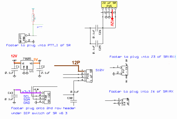
C:\Users\Rob\Documents\HamStuff\SDR\MOBO4_x\mobo43
(above schematic has clickable areas that can be used for navigation)
(go directly to build notes)Analog Power Busses Bill of Materials
Stage Bill of Materials
(resistor images and color codes courtesy of WIlfried, DL5SWB's R-Color Code program)
| Check | Count | Component | Marking | Category |
|---|---|---|---|---|
| ❏ | 1 | 1N5822 Shottky 3A diode | 1N5822 | Axial |
| ❏ | 1 | header, 2-pin |
 | Header |
| ❏ | 1 | header, 2-pin |
 | Header |
| ❏ | 2 | header, 2-pin RA |
 | Header |
| ❏ | 1 | header, 3-pin |
 | Header |
| ❏ | 1 | header, 4-pin |
 | Header |
| ❏ | 1 | header, 4-pin |
 | Header |
| ❏ | 1 | header, 5-pin |
 | Header |
| ❏ | 1 | header,right_angle, 3-pin |
 | Header |
| ❏ | 2 | header,right_angle, 3-pin |
 | Header |
| ❏ | 1 | misc hookup wire | Hookup | |
| ❏ | 1 | shunt, 2-pin |
 | Shunt |
| ❏ | 4 | 0.1 uF | SMT 0805 | |
| ❏ | 1 | 4.7 k ohm 5% | SMT 0805 1/8W | |
| ❏ | 2 | 0.1 uF | (smt) black stripe
 | SMT 1206 |
| ❏ | 1 | header socket, female, 4-pin |
 | Socket |
| ❏ | 1 | header socket,female, 2 pin |
 | Socket |
| ❏ | 1 | 7805 voltage regulator | 7805
 | TO-220 |
Analog Power Busses Summary Build Notes
- Install Bottomside Rs, Cs, and Ics
- Install topside Rs and Cs
- Install 5V Voltage Regulator
- Prepare SR RXTX Board
- Install Board Interconnect Headers ("Footers")
- Test the Stage
Analog Power Busses Detailed Build Notes
Bottom of the Board
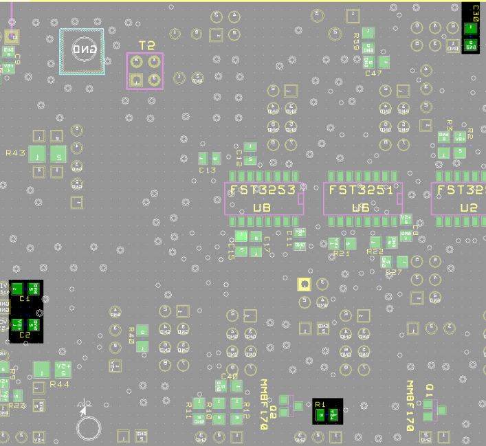
Install Bottomside Rs, Cs, and Ics
| Check | Designation | Component | Marking | Category | Orientation | Notes |
|---|---|---|---|---|---|---|
| ❏ | C01 | 0.1 uF | SMT 0805 | |||
| ❏ | C02 | 0.1 uF | SMT 0805 | |||
| ❏ | C30 | 0.1 uF | SMT 0805 | |||
| ❏ | R01 | 4.7 k ohm 5% | SMT 0805 1/8W |
Top of the Board
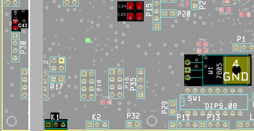
Install topside Rs and Cs
| Check | Designation | Component | Marking | Category | Orientation | Notes |
|---|---|---|---|---|---|---|
| ❏ | C24 | 0.1 uF | (smt) black stripe
 | SMT 1206 | ||
| ❏ | C25 | 0.1 uF | (smt) black stripe
 | SMT 1206 | ||
| ❏ | C43 | 0.1 uF | SMT 0805 | |||
| ❏ | K01_Shunt | shunt, 2-pin |
 | Shunt | Normal placement is on K1-1 and K1-2 | |
| ❏ | K01 | header,right_angle, 3-pin |
 | Header | Normal operation: jumper across Pins 1 and 2 |
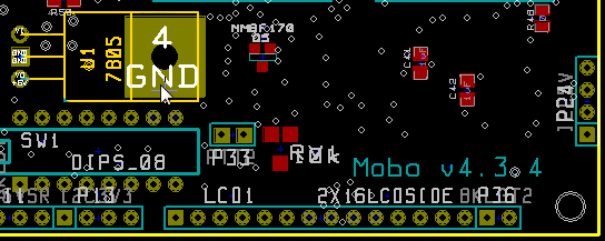
Install 5V Voltage Regulator
| Check | Designation | Component | Marking | Category | Orientation | Notes |
|---|---|---|---|---|---|---|
| ❏ | U01 | 7805 voltage regulator | 7805
 | TO-220 | Take ESD precautions |
Prepare SR RXTX Board
This step prepares the RXTX board to accept the I2C bus lines and the PTT-I signal from the MOBO. It assumes you have already built the RXTX board (without the DIP switch or with the DIP switch removed) and with all of the jacks (J1-J4 installed.
Don't forget to remove the PIC (U6) from its socket on the RXTX before plugging in the MOBO - it is not needed when the MOBO is "in control". If concurrently building the RXTX V6.3, do not install the DIP switch and the PIC chip socket. If you have installed the PIC chip, you can just remove it from the socket and leave the socket there.
There is a jumper to select between +5V and +3v3 for pin 1 of the 4- pin header in the 2nd row under the DIP switch. Solder the jumper for +3v3.
The 6 footers of the Mobo mate with 6 corresponding female receptacles on the SR v6.3. Solder the receptacles with care to ensure they are perfectly perpendicular to the pcb. This will make it easier to have a perfect mating with the footers from the Mobo.
Use right angled header connectors for I/Q input and output pins, the +12V/GND power connector, and the ANT connector, as these connections have to emerge from underneath the Mobo.
One final modification to the RXTX V6.3 board is the replacement of the 1n4003 reverse polarity protection diode with a Schottky diode (3A current rating) or a !N5819 1A diode. This change will allow increased max RF power output from the Mobo, by at least 0.5W.
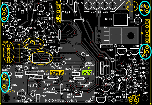
| Check | Designation | Component | Marking | Category | Orientation | Notes |
|---|---|---|---|---|---|---|
| ❏ | Dxx | 1N5822 Shottky 3A diode | 1N5822 | Axial | User-provided replacement fot RXTX V6.3's D1 | |
| ❏ | P32_Mate | header socket,female, 2 pin |
 | Socket | Prepare the SR PTT_I/GND with mating female receptacle | |
| ❏ | P30_Mate | header socket, female, 4-pin |
 | Socket | Prepare the 2nd row under DIP of SR RFXTX to accept the 4 pin footer for I2C bus | |
| ❏ | JP1 | misc hookup wire | Hookup | Install a pice of hookup wire at JP1 to provide 3.3Vdc to P30's pin 1. | ||
| ❏ | ANT | header, 2-pin RA |
 | Header | Recommended; Not supplied with kit | |
| ❏ | SR_PWR | header, 2-pin RA |
 | Header | Recommended; Not supplied with kit | |
| ❏ | IQ_RX | header,right_angle, 3-pin |
 | Header | Recommended; Not supplied with kit | |
| ❏ | IQ_TX | header,right_angle, 3-pin |
 | Header | Recommended; Not supplied with kit |
Install Board Interconnect Headers ("Footers")
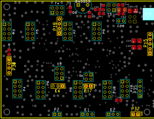
This step installs the 6 sets of male header pins that serve as "footers" for the MOBO's connections to the SR RXTX. All of the footers are installed with their long pins protruding from the bottom of the MOBO board and their short pins soldered into the MOBO boards holes. Footer locations are shown in the graphic.
As an aid to getting correct footer alignment, plug each of the 6 male footers (P15, P17,K4, P19, P30, P32) into the corresponding female receptacles on the SR RXTX v6.3, using the SR as a "jig" to hold the pins in correct alignment for soldering. Then solder the footers onto the MOBO4.3 board while they are plugged into the SR receptacles.
.
| Check | Designation | Component | Marking | Category | Orientation | Notes |
|---|---|---|---|---|---|---|
| ❏ | P19 | header, 4-pin |
 | Header | J1 of SR (footer) Connects to J1 on RXTX (S12V and QSE I and Q signals) | |
| ❏ | P15 | header, 5-pin |
 | Header | J2 of SR (footer) Connects to J2 of SR RXTX V6.3 | |
| ❏ | P17 | header, 2-pin |
 | Header | J3 of SR (footer) Connects to RXTX J3 (Ant and Gnd) | |
| ❏ | K04 | header, 3-pin |
 | Header | J4 of SR (footer) Connects to J4 of Softrock RXTX V6.3 (to QSD) | |
| ❏ | P30 | header, 4-pin |
 | Header | I2C connector (footer) Footer to plug into 2nd row under DIP of SR RFXTX | |
| ❏ | P32 | header, 2-pin |
 | Header | Footer to plug into SR PTT_I Prepare the SR PTT_I/GND with mating female receptacle |
Analog Power Busses Completed Stage
Top of the Board
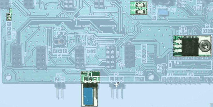
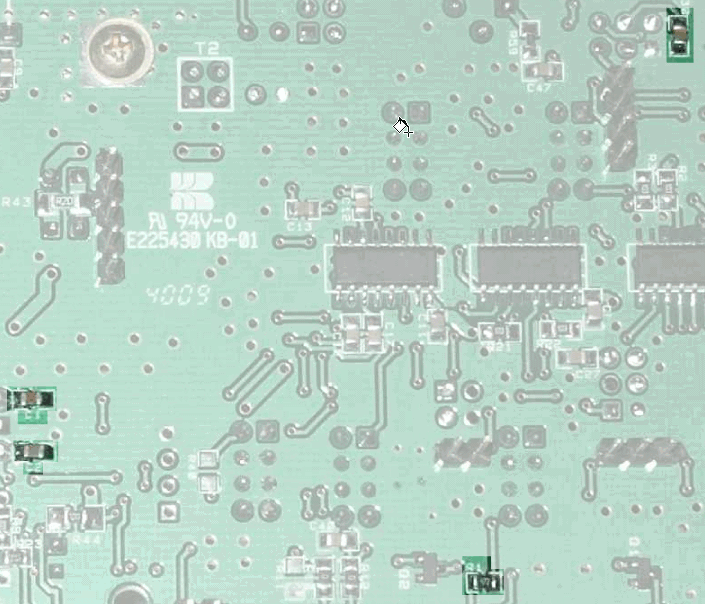
Bottom of the Board
Analog Power Busses Testing
Voltage tests
Test Setup
Using your DMM and connecting the board to the RXTX V6.3, power up the RXTX V6.3
Measure the rail voltages (with respect to analog ground) at the testpoints indicated in the graphic belowNote (tx to Mike Collins, KF4BQ): If you happened to get around 0V on P32-1 wrt P32-2, you may have missed installing R01. That is the pullup on the PTT signal for the MOBO. If R01 is installed the voltage should be 3.6V: ((5V - Vbe)* 10K/14.7K)+.Vbe)
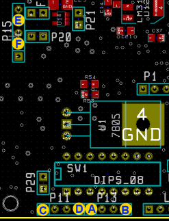
Test Measurements
| Testpoint | Units | Nominal Value | Author's | Yours |
|---|---|---|---|---|
| Pin 1 (rightmost pin) wrt Pin 2 (leftmost pin) of P32 | V dc | ~3.6 | tbd | _______ |
| Point A with respect to Point B | V dc | 3.3 | tbd | _______ |
| Point C with Respect to Point D | V dc | 5 | tbd | _______ |
| Point E with respect to Point F | V dc | 12 | tbd | _______ |