Power/SWR Control Introduction
General
It is always a good idea to double check the bill of materials in this set of documentation with the official BOM on the Mobo site. Discrepancies may be introduced inadvertently, as the changes are sometimes not communicated or discovered, making timely update of this site a problem.
Instructions for Building the POSWR Board
These WB5RVZ notes deal only with the build of the non-optional parts of the MOBO. Building the POSWR "subboard" is optional. This optional board may be built per Graeme's (ZL2APV) POSWR Build Instructions found in the MOBO Google Group (you must be loggedin member of the group to use the link).
The POSWR schematic is available in the group's files as well.
Other valueable references for the optional SWR Board include:
- Picture of completed POSWR Board
- Another Completed POSWR Picture (tx Graeme ZL2APV)
- Ray's (W7RJC) Picture of Completed Board
- Ray's Picture of Parts Layout for the Board
Power/SWR Control Schematic
(Click for Full Schematic)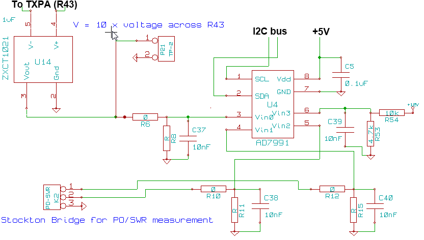
C:\Users\Rob\Documents\HamStuff\SDR\MOBO4_x\mobo43
(above schematic has clickable areas that can be used for navigation)
(go directly to build notes)Power/SWR Control Bill of Materials
Stage Bill of Materials
(resistor images and color codes courtesy of WIlfried, DL5SWB's R-Color Code program)
| Check | Count | Component | Marking | Category |
|---|---|---|---|---|
| ❏ | 1 | header, 2-pin |
 | Header |
| ❏ | 1 | header,right_angle, 3-pin |
 | Header |
| ❏ | 1 | housing, female, 3-pin |
 | Housing |
| ❏ | 4 | 0.01 uF | SMT 0805 | |
| ❏ | 1 | 0.1 uF | SMT 0805 | |
| ❏ | 2 | 0 ohm 5% | SMT 0805 1/8W | |
| ❏ | 1 | 0 ohm 5% | SMT 0805 1/8W | |
| ❏ | 1 | 10 k ohm 5% | SMT 0805 1/8W | |
| ❏ | 1 | 4.7 k ohm 5% | SMT 0805 1/8W | |
| ❏ | 1 | AD7991 ADC 12BIT 4CH I2C | AD7991
 | SOT-23-8 |
Power/SWR Control Summary Build Notes
- Install Bottomside IC
- Install Bottomside Static Components
- Install topside IC
- Install Topside Static Components
- Test the Stage
Power/SWR Control Detailed Build Notes
Bottom of the Board
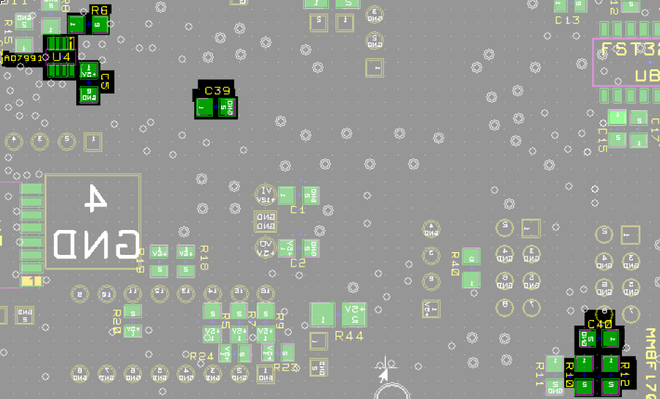
Install Bottomside IC
| Check | Designation | Component | Marking | Category | Orientation | Notes |
|---|---|---|---|---|---|---|
| ❏ | U04 | AD7991 ADC 12BIT 4CH I2C | AD7991
 | SOT-23-8 | Take ESD precautions |
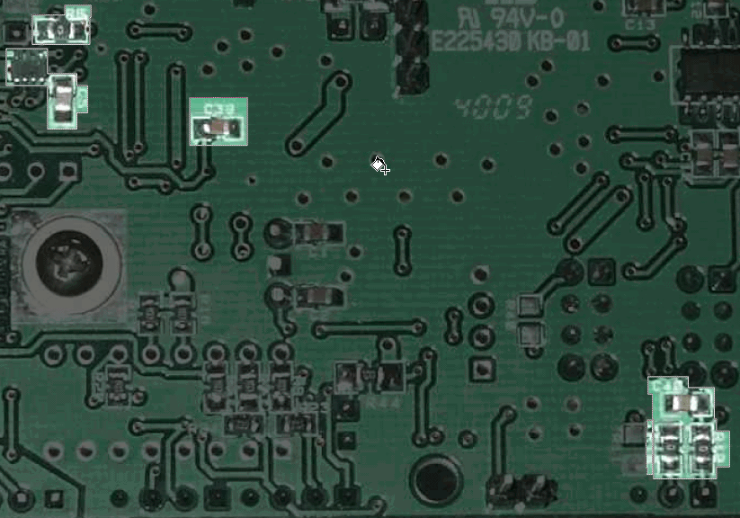
Install Bottomside Static Components
| Check | Designation | Component | Marking | Category | Orientation | Notes |
|---|---|---|---|---|---|---|
| ❏ | C05 | 0.1 uF | SMT 0805 | |||
| ❏ | C39 | 0.01 uF | SMT 0805 | |||
| ❏ | C40 | 0.01 uF | SMT 0805 | |||
| ❏ | R06 | 0 ohm 5% | SMT 0805 1/8W | see note #3; Lyle, KK7P recommends deferring mounting R6 due to the nearby IC | ||
| ❏ | R10 | 0 ohm 5% | SMT 0805 1/8W | see note #3 | ||
| ❏ | R12 | 0 ohm 5% | SMT 0805 1/8W | see note #3 |
Top of the Board
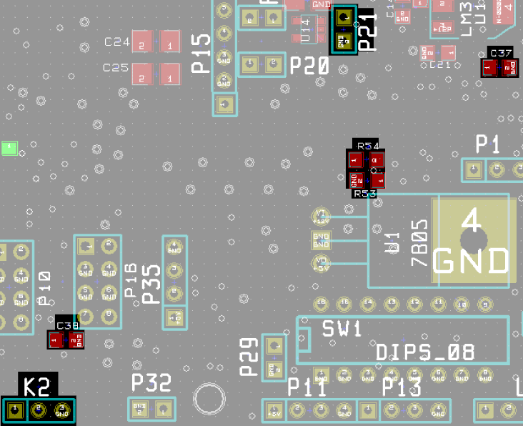
Install topside IC
U14, while electronically included in this stage, was physically installed in the preceding stage, due to the need to avoid crowding by neighboring components.
Install Topside Static Components
| Check | Designation | Component | Marking | Category | Orientation | Notes |
|---|---|---|---|---|---|---|
| ❏ | C37 | 0.01 uF | SMT 0805 | |||
| ❏ | C38 | 0.01 uF | SMT 0805 | |||
| ❏ | R53 | 4.7 k ohm 5% | SMT 0805 1/8W | |||
| ❏ | R54 | 10 k ohm 5% | SMT 0805 1/8W | |||
| ❏ | K02 | header,right_angle, 3-pin |
 | Header | Connect to P1 of POSWR board (optional). Note Pin 3 (GND) is connected to Pin 1 (GND) of POSWR board, Pin 2 to Pin 2, and Pin 1 (FWD) to Pin 3 of POSWR board | |
| ❏ | K02_Mate | housing, female, 3-pin |
 | Housing | ||
| ❏ | P21 | header, 2-pin |
 | Header | TP2 - Drain Current Test Point 2 Voltage of Pin 1 is 10 times voltage across R43 |
Power/SWR Control Completed Stage
Top of the Board
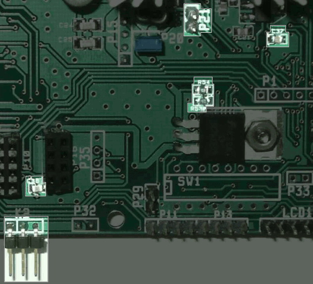
Bottom of the Board
Power/SWR Control Testing
Test Program Requirements
Test Setup
- Program should allow the user to measure and display the voltage drop ocross R43, as sensed by U14 through U4
- Program should allow the user to (using a slider or similar control) vary the bias voltage to the driver transistoir, regardless of the temperature sensor's output.