Dividers Introduction
General
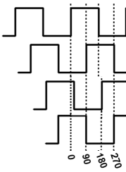
This phase installs the flip flop dividers, which divide the local oscillator's output into four quadrature signals, each at a frequency of exactly one-fourth the LO frequency and each 90 degrees out of phase with the other (0, 90, 180, 270):

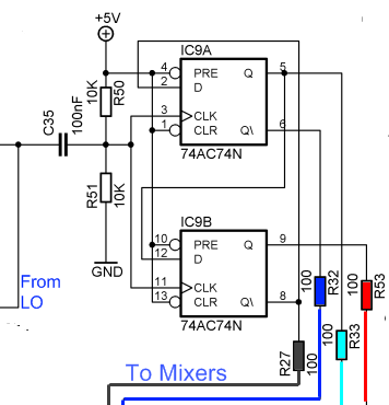
The four divider outputs are color-coded on the schematic below, a color-coding scheme that will be used, as well, in the follow-on Mixer Phase.
These signals will be used to clock the quad bilateral switches in the mixer stage, which is closely patterned after the Tayloe detector (see discussion at page 18 of "A Software Defined Radio for the Masses, Part I"
(go directly to build notes)Dividers Schematic

(go directly to build notes)
Dividers Bill of Materials
Stage Bill of Materials
(resistor images and color codes courtesy of WIlfried, DL5SWB's R-Color Code program)
| Check | Count | Component | Marking | Category |
|---|---|---|---|---|
| ❏ | 4 | 100 1/4W 1% | br-blk-blk-blk-br
 | 1/4W |
| ❏ | 2 | 220 1/4W 1% | red-red-blk-blk-brn
 | 1/4W |
| ❏ | 1 | 10 nF (.01uF) | 103
 | Ceramic |
| ❏ | 4 | 100 nF | 104
 | Ceramic |
| ❏ | 2 | 47 uH molded inductor 10% | yel-vio-blk-slv
 | Choke |
| ❏ | 1 | 74AC(HC)74 Dual-D FF | 74HC74 or 74AC74
 | DIP-14 |
| ❏ | 1 | 100 uF/25Vdc |
 | Electrolytic |
| ❏ | 1 | 220 uF/16Vdc |
 | Electrolytic |
Dividers Summary Build Notes
- Install Resistors
- Install Chokes
- Install Ceramic Capacitors
- Install IC 74AC74PC
- Install Electolytic Capacitors
- Inspected Completed Board
- Test the Stage
Dividers Detailed Build Notes
Top of the Board

Install Resistors
| Check | Designation | Component | Marking | Category | Orientation | Notes |
|---|---|---|---|---|---|---|
| ❏ | R4-1 | 100 1/4W 1% | br-blk-blk-blk-br
 | 1/4W | ||
| ❏ | R4-2 | 100 1/4W 1% | br-blk-blk-blk-br
 | 1/4W | ||
| ❏ | R4-3 | 100 1/4W 1% | br-blk-blk-blk-br
 | 1/4W | ||
| ❏ | R4-4 | 100 1/4W 1% | br-blk-blk-blk-br
 | 1/4W | ||
| ❏ | R4-5 | 220 1/4W 1% | red-red-blk-blk-brn
 | 1/4W | ||
| ❏ | R4-6 | 220 1/4W 1% | red-red-blk-blk-brn
 | 1/4W |
Install Chokes
Do not confuse with the 470 nH choke!
| Check | Designation | Component | Marking | Category | Orientation | Notes |
|---|---|---|---|---|---|---|
| ❏ | L4-1 | 47 uH molded inductor 10% | yel-vio-blk-slv
 | Choke | ||
| ❏ | L4-2 | 47 uH molded inductor 10% | yel-vio-blk-slv
 | Choke |
Install Ceramic Capacitors
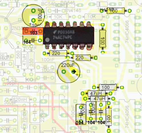
Note: the 10 nF capacitor is shaded a different color and marked "103" on the board layout graphic.
| Check | Designation | Component | Marking | Category | Orientation | Notes |
|---|---|---|---|---|---|---|
| ❏ | C4-1 | 10 nF (.01uF) | 103
 | Ceramic | (just below 100 uF Electrolytic) | |
| ❏ | C4-2 | 100 nF | 104
 | Ceramic | ||
| ❏ | C4-3 | 100 nF | 104
 | Ceramic | ||
| ❏ | C4-4 | 100 nF | 104
 | Ceramic | ||
| ❏ | C4-5 | 100 nF | 104
 | Ceramic |
Install IC 74AC74PC
| Check | Designation | Component | Marking | Category | Orientation | Notes |
|---|---|---|---|---|---|---|
| ❏ | U4-1 | 74AC(HC)74 Dual-D FF | 74HC74 or 74AC74
 | DIP-14 | (notch toward 100 uF electrolytic) | Take ESD precautions |
Install Electolytic Capacitors
Take care to respect polarity - see board layout
| Check | Designation | Component | Marking | Category | Orientation | Notes |
|---|---|---|---|---|---|---|
| ❏ | C4-6 | 100 uF/25Vdc |
 | Electrolytic | ||
| ❏ | C4-7 | 220 uF/16Vdc |
 | Electrolytic |
Dividers Testing
Voltage Tests
Test Setup
Select a frequency in the oscillator and measure the voltage with respect to ground at each of the pins on IC9
Test Measurements
| Testpoint | Units | Nominal Value | Author's | Yours |
|---|---|---|---|---|
| IC9-9 | Vdc | 2.5 | 2.54 | _______ |
| IC9-7 | Vdc | 0 | 0 | _______ |
| IC9-6 | Vdc | 2.5 | 2.44 | _______ |
| IC9-5 (and IC9-12) | Vdc | 2.5 | 2.5 | _______ |
| IC9-3 (and IC9-11) | Vdc | 2.5 | 2.51 | _______ |
| IC9-2 (and IC9-8) | Vdc | 2.5 | 2.42 | _______ |
| IC9-1 (and IC9-4, IC9-10, IC9-13, and IC9-14) | Vdc | 5 | 5.01 | _______ |
Check for Frequency
Test Setup
Tune HF receiver to detect the signals from the dividers by selecting one frequency of G3020 oscillator at a time. You should hear signals on (in order of selected oscillator):
- 30m: 10.125 MHz
- 20m: 14.045 MHz
- 20m: 14.138 MHz
- 20m: 14.232 MHz
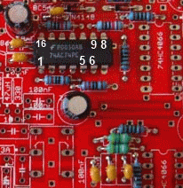
You may need to use a clip lead as an "antenna", clipping it to any of pins 5, 6, 8, or 9 on the 74AC74 divider IC. Each pin has the identical signal but the signals each correspond to different phases (0, 90, 180, or 270 degrees).
