TX Sample and Hold Introduction
General
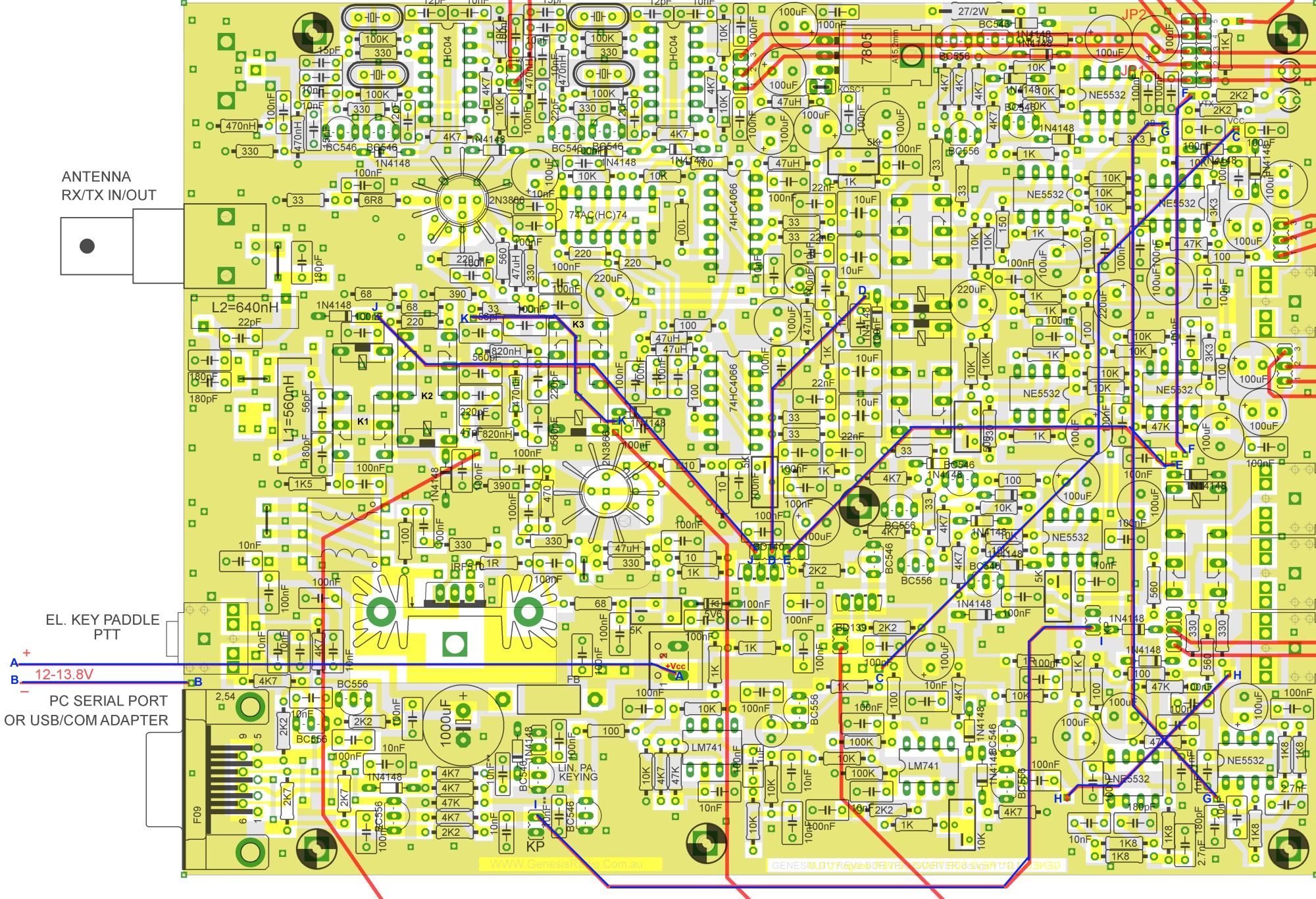
This phase takes two signals (I and Q) from the PC Soundcard and produces four quadrature outputs to the bilateral mixing switches. The process is essentially the reverse of the RX side. Since the mixers are bilateral, the TX signals in quadrature go through the same process of sampling and holding, clocked by the Quadrature signals from the dividers.
This stage appears in three different areas of the board, all near the right-hand edge. The areas are referred to below as the "top thirs, the middle third, and the bottom third of the board.
 (go directly to build notes)
TX Sample and Hold Schematic
(go directly to build notes)
TX Sample and Hold Bill of Materials
Stage Bill of Materials
(resistor images and color codes courtesy of WIlfried, DL5SWB's R-Color Code program)
| Check | Count | Component | Marking | Category |
|---|---|---|---|---|
| ❏ | 1 | 1 k 1/4W 1% | br-blk-blk-br-br
 | 1/4W |
| ❏ | 4 | 100 1/4W 1% | br-blk-blk-blk-br
 | 1/4W |
| ❏ | 6 | 10K 1/4W 1% | brn-blk-blk-red-brn
 | 1/4W |
| ❏ | 6 | 1K8 (1.8k) 1/4W 1% | brn-gry-blk-brn-brn
 | 1/4W |
| ❏ | 3 | 33 1/4W 1% | ora-ora-blk-gld-brn
 | 1/4W |
| ❏ | 1 | 3k3 1/4W 1% (3.3K) | ora-ora-blk-brn-brn
 | 1/4W |
| ❏ | 2 | 47K 1/4W 1% | yel-vio-blk-red-brn
 | 1/4W |
| ❏ | 8 | 4K7 1/4W 1% (4.7K) | yel-vio-blk-brn-brn
 | 1/4W |
| ❏ | 1 | 560 1/4W 1% | grn-blu-blk-blk-brn
 | 1/4W |
| ❏ | 1 | 560 1/4W 1% | grn-blu-blk-blk-brn
| 1/4W |
| ❏ | 8 | 1N4148 | 1N4148
 | Axial |
| ❏ | 1 | 1N4148 | 1N4148
| Axial |
| ❏ | 1 | 10 nF (.01uF) | 103
 | Ceramic |
| ❏ | 1 | 100 nF | 104
 | Ceramic |
| ❏ | 3 | 100 nF | 104
| Ceramic |
| ❏ | 1 | 100 nF | 104
| Ceramic |
| ❏ | 2 | NE5532 Dual OpAmp | NE5532
 | DIP-8 |
| ❏ | 2 | NE5532 Dual OpAmp | NE5532
| DIP-8 |
| ❏ | 7 | 100 uF/25Vdc |
 | Electrolytic |
| ❏ | 2 | misc hookup wire | Hookup | |
| ❏ | 2 | 1 nF USM | 102J
 | Metalized polyfilm |
| ❏ | 2 | 10 nF USM | 103J
 | Metalized polyfilm |
| ❏ | 2 | 100 nF USM | 104J
 | Metalized polyfilm |
| ❏ | 2 | 180 pF USM | 181K
 | Metalized polyfilm |
| ❏ | 2 | 2.7 nF USM | 272J
 | Metalized polyfilm |
| ❏ | 4 | BC546 NPN Transistor |
| TO-92 |
| ❏ | 4 | BC556 PNP Transistor |
| TO-92 |
| ❏ | 1 | 5K (Y502) | Y502
 | Trimpot |
TX Sample and Hold Summary Build Notes
- Install Top Third Active Components
- Install Top Third Passive Components
- Install Middle Third Active Components
- Install Middle Third Passive Components
- Install Bottom Third Active Components
- Install Bottom Third Passive Components
- Install Connecting Wires
- Test the Stage
TX Sample and Hold Detailed Build Notes
Top of the Board
Install Top Third Active Components
| Check | Designation | Component | Marking | Category | Orientation | Notes |
|---|---|---|---|---|---|---|
| ❏ | Q9-1 | BC556 PNP Transistor |
| TO-92 | ||
| ❏ | Q9-2 | BC556 PNP Transistor |
| TO-92 | ||
| ❏ | Q9-3 | BC546 NPN Transistor |
| TO-92 | ||
| ❏ | Q9-4 | BC546 NPN Transistor |
| TO-92 | ||
| ❏ | U9-1 | NE5532 Dual OpAmp | NE5532
| DIP-8 | Take ESD precautions |
Install Top Third Passive Components
| Check | Designation | Component | Marking | Category | Orientation | Notes |
|---|---|---|---|---|---|---|
| ❏ | D9-4 | 1N4148 | 1N4148
| Axial | ||
| ❏ | C9-16 | 100 uF/25Vdc |
| Electrolytic | ||
| ❏ | C9-17 | 100 uF/25Vdc |
| Electrolytic | ||
| ❏ | D9-1 | 1N4148 | 1N4148
| Axial | ||
| ❏ | D9-2 | 1N4148 | 1N4148
| Axial | ||
| ❏ | D9-3 | 1N4148 | 1N4148
| Axial | ||
| ❏ | C9-10 | 100 nF | 104
| Ceramic | ||
| ❏ | R9-4 | 100 1/4W 1% | br-blk-blk-blk-br
| 1/4W | ||
| ❏ | R9-17 | 4K7 1/4W 1% (4.7K) | yel-vio-blk-brn-brn
| 1/4W | ||
| ❏ | R9-18 | 4K7 1/4W 1% (4.7K) | yel-vio-blk-brn-brn
| 1/4W | ||
| ❏ | R9-19 | 4K7 1/4W 1% (4.7K) | yel-vio-blk-brn-brn
| 1/4W | ||
| ❏ | R9-20 | 4K7 1/4W 1% (4.7K) | yel-vio-blk-brn-brn
| 1/4W | ||
| ❏ | R9-1 | 33 1/4W 1% | ora-ora-blk-gld-brn
| 1/4W | ||
| ❏ | R9-2 | 33 1/4W 1% | ora-ora-blk-gld-brn
| 1/4W | ||
| ❏ | R9-25 | 10K 1/4W 1% | brn-blk-blk-red-brn
| 1/4W | ||
| ❏ | R9-26 | 10K 1/4W 1% | brn-blk-blk-red-brn
| 1/4W | ||
| ❏ | R9-27 | 10K 1/4W 1% | brn-blk-blk-red-brn
| 1/4W | ||
| ❏ | R9-16 | 3k3 1/4W 1% (3.3K) | ora-ora-blk-brn-brn
| 1/4W |
Install Middle Third Active Components
| Check | Designation | Component | Marking | Category | Orientation | Notes |
|---|---|---|---|---|---|---|
| ❏ | Q9-5 | BC556 PNP Transistor |
| TO-92 | ||
| ❏ | Q9-6 | BC556 PNP Transistor |
| TO-92 | ||
| ❏ | Q9-7 | BC546 NPN Transistor |
| TO-92 | ||
| ❏ | Q9-8 | BC546 NPN Transistor |
| TO-92 | ||
| ❏ | U9-2 | NE5532 Dual OpAmp | NE5532
| DIP-8 | Take ESD precautions | |
| ❏ | R9-33 | 5K (Y502) | Y502
| Trimpot | Needs to be initialized. Before installing this trimmer, adjust the resistance between the middle pin and either of the other pins to 2.5 K Ohm. |
Install Middle Third Passive Components
In the component placement diagram on the website, there is a 100nF capacitor immediately to the left of the 5K trim pot. The diagram shows it as horizontally oriented but the latest version of the actual PCB shows it in a vertical orientation. There was a change in the PCB after the documentation herein was published. (TX to Al WA8LBZ for this tip)
| Check | Designation | Component | Marking | Category | Orientation | Notes |
|---|---|---|---|---|---|---|
| ❏ | D9-10 | 1N4148 | 1N4148
| Axial | (reloc) | |
| ❏ | D9-5 | 1N4148 | 1N4148
| Axial | ||
| ❏ | D9-6 | 1N4148 | 1N4148
| Axial | ||
| ❏ | D9-7 | 1N4148 | 1N4148
| Axial | ||
| ❏ | D9-8 | 1N4148 | 1N4148
| Axial | ||
| ❏ | C9-7 | 10 nF (.01uF) | 103
| Ceramic | ||
| ❏ | C9-11 | 100 nF | 104
| Ceramic | ||
| ❏ | C9-12 | 100 nF | 104
| Ceramic | ||
| ❏ | C9-18 | 100 uF/25Vdc |
| Electrolytic | ||
| ❏ | C9-19 | 100 uF/25Vdc |
| Electrolytic | ||
| ❏ | R9-21 | 4K7 1/4W 1% (4.7K) | yel-vio-blk-brn-brn
| 1/4W | ||
| ❏ | R9-22 | 4K7 1/4W 1% (4.7K) | yel-vio-blk-brn-brn
| 1/4W | ||
| ❏ | R9-23 | 4K7 1/4W 1% (4.7K) | yel-vio-blk-brn-brn
| 1/4W | ||
| ❏ | R9-24 | 4K7 1/4W 1% (4.7K) | yel-vio-blk-brn-brn
| 1/4W | ||
| ❏ | R9-3 | 33 1/4W 1% | ora-ora-blk-gld-brn
| 1/4W | ||
| ❏ | R9-5 | 100 1/4W 1% | br-blk-blk-blk-br
| 1/4W | ||
| ❏ | R9-28 | 10K 1/4W 1% | brn-blk-blk-red-brn
| 1/4W | ||
| ❏ | R9-29 | 10K 1/4W 1% | brn-blk-blk-red-brn
| 1/4W | ||
| ❏ | R9-30 | 10K 1/4W 1% | brn-blk-blk-red-brn
| 1/4W | ||
| ❏ | R9-8 | 560 1/4W 1% | grn-blu-blk-blk-brn
| 1/4W | ||
| ❏ | R9-9 | 1 k 1/4W 1% | br-blk-blk-br-br
| 1/4W |
Install Bottom Third Active Components
| Check | Designation | Component | Marking | Category | Orientation | Notes |
|---|---|---|---|---|---|---|
| ❏ | U9-3 | NE5532 Dual OpAmp | NE5532
| DIP-8 | Take ESD precautions | |
| ❏ | U9-4 | NE5532 Dual OpAmp | NE5532
| DIP-8 | Take ESD precautions | |
| ❏ | C9-3 | 1 nF USM | 102J
| Metalized polyfilm |
Install Bottom Third Passive Components
| Check | Designation | Component | Marking | Category | Orientation | Notes |
|---|---|---|---|---|---|---|
| ❏ | C9-13 | 100 nF | 104
| Ceramic | ||
| ❏ | C9-4 | 1 nF USM | 102J
| Metalized polyfilm | ||
| ❏ | C9-5 | 2.7 nF USM | 272J
| Metalized polyfilm | ||
| ❏ | C9-6 | 2.7 nF USM | 272J
| Metalized polyfilm | ||
| ❏ | C9-8 | 10 nF USM | 103J
| Metalized polyfilm | ||
| ❏ | C9-9 | 10 nF USM | 103J
| Metalized polyfilm | ||
| ❏ | C9-23 | 100 nF | 104
| Ceramic | (reloc) | |
| ❏ | C9-14 | 100 nF USM | 104J
| Metalized polyfilm | ||
| ❏ | C9-15 | 100 nF USM | 104J
| Metalized polyfilm | ||
| ❏ | C9-1 | 180 pF USM | 181K
| Metalized polyfilm | ||
| ❏ | C9-2 | 180 pF USM | 181K
| Metalized polyfilm | ||
| ❏ | C9-20 | 100 uF/25Vdc |
| Electrolytic | ||
| ❏ | C9-21 | 100 uF/25Vdc |
| Electrolytic | ||
| ❏ | C9-22 | 100 uF/25Vdc |
| Electrolytic | ||
| ❏ | R9-10 | 1K8 (1.8k) 1/4W 1% | brn-gry-blk-brn-brn
| 1/4W | ||
| ❏ | R9-11 | 1K8 (1.8k) 1/4W 1% | brn-gry-blk-brn-brn
| 1/4W | ||
| ❏ | R9-12 | 1K8 (1.8k) 1/4W 1% | brn-gry-blk-brn-brn
| 1/4W | ||
| ❏ | R9-13 | 1K8 (1.8k) 1/4W 1% | brn-gry-blk-brn-brn
| 1/4W | ||
| ❏ | R9-14 | 1K8 (1.8k) 1/4W 1% | brn-gry-blk-brn-brn
| 1/4W | ||
| ❏ | R9-15 | 1K8 (1.8k) 1/4W 1% | brn-gry-blk-brn-brn
| 1/4W | ||
| ❏ | R9-6 | 100 1/4W 1% | br-blk-blk-blk-br
| 1/4W | ||
| ❏ | R9-7 | 100 1/4W 1% | br-blk-blk-blk-br
| 1/4W | ||
| ❏ | R9-34 | 560 1/4W 1% | grn-blu-blk-blk-brn
| 1/4W | ||
| ❏ | R9-31 | 47K 1/4W 1% | yel-vio-blk-red-brn
| 1/4W | ||
| ❏ | R9-32 | 47K 1/4W 1% | yel-vio-blk-red-brn
| 1/4W |
Install Connecting Wires
Install Connecting wires
In this step you must install two connecting wires. The Genesis-Radio site's documentation refers to these as "W8" and "W9". The graphic in these notes refer to the wires by their end-points:
- W8 is shown in the graphic as having end-points named "G"
- W9 uses the letter "C" for its end-point names \
W8 (Endpoints = "G")
Install connecting wire W8 between the two points marked "G"
These two points are shown, blown up, here:
W9 (Endpoints = "C")
Install connecting wire W9 between the two points marked "C"
These two points are shown, blown up, here:
| Check | Designation | Component | Marking | Category | Orientation | Notes |
|---|---|---|---|---|---|---|
| ❏ | W8 | misc hookup wire | Hookup | |||
| ❏ | W9 | misc hookup wire | Hookup |
TX Sample and Hold Testing
TX IQ Balance Resistance Adjustment
Test Setup
Power is OFF for this test
Make sure the G3020 is NOT connected to the sound card
This step adjusts the trimmer pot resistance in the TX IQ Balance Circuit. The intent is to have the resistance represented as "R12" equal the series resistance represented by the trimmer pot "R67" and the resistor "R60". The adjustment varys the trimmer until the series resistance is 3.3k ohms.
Test points are indicated as A and B in the graphic.
Measure the resistance while adjusting until it reads 3.3K ohms
Test Measurements
| Testpoint | Units | Nominal Value | Author's | Yours |
|---|---|---|---|---|
| A and B: measure resistance | ohms | 3.3k | tbd | _______ |
Voltage Tests
Test Setup
Apply power to the board and measure the voltages at the test points
Test Measurements
| Testpoint | Units | Nominal Value | Author's | Yours |
|---|---|---|---|---|
| "A" (33 ohm resistor in top third | Vdc | 6.1 | tbd | _______ |
| "B" (33 ohm resistor in top third | Vdc | 6.1 | tbd | _______ |
| "C" (33 ohm resistor in middle third | Vdc | 6.1 | tbd | _______ |
| "D" (33 ohm resistor in middle third | Vdc | 6.1 | tbd | _______ |