GenesisRadio G3020 30/20m Transceiver Introduction
General
Search GenesisRadio and WB5RVZ Sites
Use this search box to search for information available on the GenesisRadio.com and WB5RVZ.com websites related to this radio kit.
Theory of Operation
Click on the elements of the block diagram below to view the details of the various stages of the build. Each stage has an introductory section discussing details of the stage and/or its theory of operation.
(Errata: the diagrams label the PA_RXTX Control" stage as "PC ...". Please mentally replace the "PC ... " in the graphics to "PA ... ")
Final Wiring Diagram
The final wiring diagram for the completed kit is in the (large) graphic found here.
Watch out for the pre-amp and attenuator switches in the Final Diagram. In the lower right hand corner there are they are labeled PREAMP and ATTN. According to the wiring of these two switches in the diagram, the names on the two switches have been reversed. The upper switch should be labeled ATTN and the lower switch should be labeled PREAMP.
(go directly to build notes) (go directly to build notes)GenesisRadio G3020 30/20m Transceiver Bill of Materials
See Project Bill of MaterialsProject Detailed Build Notes
For the non-expert builders among us, this site takes you through a stage-by-stage build of the kit. Each stage is self-contained and outlines the steps to build and test the stage. This ensures that you will have a much better chance of success once you reach the last step, since you will have successfully built and tested each preceding stage before moving on to the next stage.
Each stage is listed below, in build order, and you can link to it by clicking on its name below (or in the header and/or footer of each web page).
- Inventory the BOM
- Build and Test the Power Supply Stage
- Build and Test the Local Oscillators Stage
- Build and Test the Band Switch Stage
- Build and Test the Dividers Stage
- Build and Test the RX Mixers/OpAmps Stage
- Build and Test the LP Filters and Pre-Amp Stage
- Build and Test the CW Monitor Stage
- Build and Test the PA RX/TX Control Stage
- Build and Test the TX Sample and Hold Stage
- Build and Test the TX Driver and PA Stage
- Build and Test the Final Step and Adjustments Stage
Background Info
Tools
Winding Inductors
To learn how to wind coils and transformers, please read the
- tips from the experts and then
- view the excellent videos on KC0WOXs Website
- or take a read of Dinesh's VU2FD guidelines.
- You can review the common construction techniques for inductors for details on deciphering the winding specifications, core specifications,and construction of toroidal and binocular inductors.
Soldering
If you are not experienced at soldering (and even if you are somewhat experienced at soldering), refer to Tom N0SS's excellent tutorial on basic soldering techniques.
The video below describes techniques for soldering SOIC 14 (and 16 and 8) SMDs
View the above in full-screen mode on Youtube.
For the more adventurous, there is a process using solder paste and an electric oven called the reflow process, which can be used to install all the SMT chips to one side of the PC Board. This is documented by Guenael Jouchet in the following Youtube segment:
- Read the Primer on SMT Soldering at the Sparkfun site. It is a very good read and it speaks great truths. Then take the time to watch the video tutorial on soldering an SOIC SMD IC.
- Solder Stations. Don't skimp here. Soldering deficiencies account for 80 percent of the
problems surfaced in troubleshooting. It is preferable to have an ESD-safe station, with a
grounded tip. A couple of good stations that are relatively inexpensive are:
-
 Velleman VTSS5U 50W Solder Station (approx $20 at Frys) (See BGMicro for Spare Tips)
 -
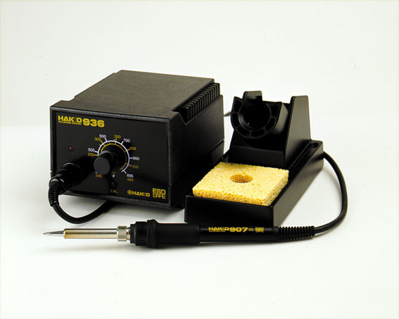 Haakko 936 ESD Solder Station (under $100)
-
ESD Protection
You may wish to review the message topic beginning at Message 43554 for a common-sense discussion on ESD.
- Avoid carpets in cool, dry areas.
- Leave PC cards and memory modules in their anti-static packaging until ready to be installed.
- Dissipate static electricity before handling any system components (PC cards, memory modules) by touching a grounded metal object, such as the system unit unpainted metal chassis.
- If possible, use antistatic devices, such as wrist straps and antistatic mats (see Radio Shack's Set for $25 or the JameCo AntiStatic mat for $15)).
- Always hold a PC card or memory module by its edges. Avoid touching the contacts and components on the memory module.
- Before removing chips from insulator, put on the wrist strap connected to the ESD mat. All work with CMOS chips should be done with the wrist strap on.
- As an added precaution before first touching a chip, you should touch a finger to a grounded metal surface.
- If using a DMM, its outside should be in contact with the ground of the ESD mat, and both leads shorted to this ground before use.
- See the review of ESD Precautions at this link.
Work Area
- You will need a well-lit work area and a minimum of 3X magnification (the author uses a cheap magnifying fluorescent light with a 3X lens. This is supplemented by a hand-held 10 X loupe - with light - for close-in inspection of solder joints and SMT installation.
- You should use a cookie sheet or baking pan (with four sides raised approximately a half an inch) for your actual work space. It is highly recommended for building on top of in order to catch stray parts, especially the tiny SMT chips which, once they are launched by an errant tweezer squeeze, are nigh on impossible to find if they are not caught on the cookie sheet.
Misc Tools
- It is most important to solidly clamp the PCB in a holder when soldering. A "third-hand" (e.g., Panavise or the Hendricks kits PCB Vise) can hold your board while soldering. In a pinch, you can get by with a simple third-hand, alligator clip vise. Jan G0BBL suggests "A very cheap way is to screw a Large Document Clip to a woodblock which will clamp the side of a PCB."
- Magnifying Head Strap
- Tweezers (bent tip is preferable).
- A toothpick and some beeswax - these can be used to pickup SMT devices and hold them steady while soldering.
- Diagonal side cutters.
- Small, rounded jaw needle-nose pliers.
- Set of jewelers' screwdrivers
- An Exacto knife.
- Fine-grit emery paper.
GenesisRadio G3020 30/20m Transceiver Testing
Each stage will have a "Testing" Section, outlining one or more tests that, when successfully completed, provide you with the confidence and assurance that you are heading in the right direction towards a fully tested and built transceiver.
When you perform a test, you should always record the results of the test where indicated in the Testing section. This will make troubleshooting via the reflector much easier, since you will be communicating with the experts using a standard testing and measurement regime.
When comparing measurements to those published in these notes, the builder should be aware that actual and expected values could vary by as much as +/- 10%. The idea behind furnishing "expected/nominal" measurement values is to provide the builder with a good, "ballpark" number to determine whether or not the test has been successful. If the builder has concerns about his measurements, he should by all means pose those concerns as a query in the Softrock reflector so the experts can provide assistance.
This kit can be built and reliably tested using nothing more than a common multimeter. Tests assume that the builder has a decent digital multimeter of sufficiently high input impedance as to minimize circuit loading issues. Measurements will be taken of current draws, test point voltages, and resistances.
Most stages will have a current draw test, in which the builder tests the stage's current draw in two different ways:
- First, testing the draw through a current-limiting resistor
- Then, when that test is OK, removing the current-limiting resistor and measuring the real current draw.
The
IQGen or DQ-Gen
programs available free from Michael Keller, DL6IAK, can be used in
a pinch to get the sound card to produce audio tones for injection into the circuit.
You can always use Rocky to generate I and Q signals for tests requiring these audio signals (this is the author's preferred way)