Final Step and Adjustments Introduction
General
Interim Instructions
Refer to the G40 kit's Final Tests and Adjustments page for guidance in completing your G3020 kit.
(go directly to build notes)Final Step and Adjustments Schematic
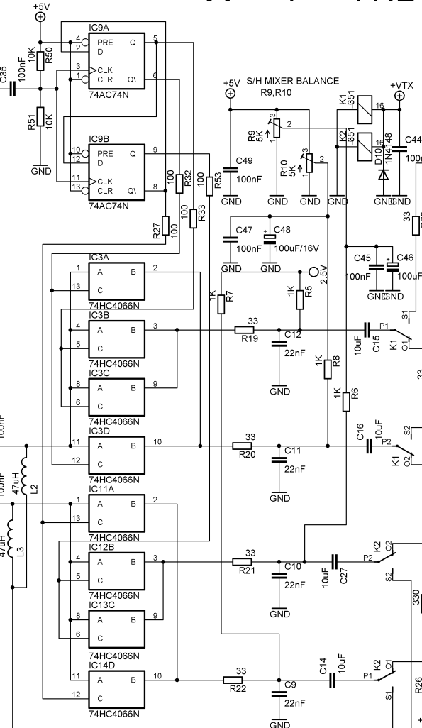
(go directly to build notes)
Final Step and Adjustments Bill of Materials
Final Step and Adjustments Detailed Build Notes
Final Step and Adjustments Testing
Test Op Amp Voltages
Test Setup
Before you can check voltage on NE5532's in this, ensure you connected all of the permanent wires specified at the end of Phase 10. Among those wires are ones which supply + voltage to the four TX NE5532 installed above. Basically make sure that you have +12 to 13V on pin 8 on all NE5532.
When we say in the following tests that "the voltage must be identical" we expect the builder to see a very close value on all pins, but NOT absolutely identical voltage. We are really looking for mismatch of lets say +/- 1V or so, which would be an indication of incorrectly placed component (most likely a resistor, diode or transistor) or faulty op amp. Because individual components used have their own tolerance, slight deviation is quite normal, expected and acceptable.
This series of tests applies equally to each of the four RX and four TX NE5532s.
- Apply power to the board.
- Check out voltage on each of the 8 ICs NE5532
- Note that the RX ICs are installed with their "1" pins at the upper right of each chip; the TX ICs are installed with the "1" pin at the lower left of each IC.
- pins 1,2,3,5,6,7. [+5.70V to + 6.00V]
- This voltage must be identical on all of the specified pins for all eight ICs.
Test Measurements
| Testpoint | Units | Nominal Value | IC-A | IC-B | IC-C | IC-D | IC-E | IC-F | IC-G | IC-H |
|---|---|---|---|---|---|---|---|---|---|---|
| Pin 1 | V dc | 6.0 | ||||||||
| Pin2 | V dc | 6.0 | ||||||||
| Pin 3 | V dc | 6.0 | ||||||||
| Pin 4 | V dc | 0 | ||||||||
| Pin 5 | V dc | 6.0 | ||||||||
| Pin 6 | V dc | 6.0 | ||||||||
| Pin 7 | V dc | 6.0 | ||||||||
| Pin 8 | V dc | 12.0 |
Perform Additional Voltage Tests
Test Setup
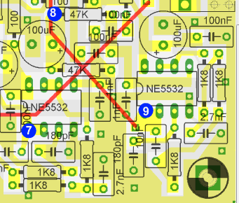
Measure the dc voltage at each of the testpoints shown in the following graphics. Each test point should have the same voltage (it will be in the range of 6.0-6.1 Vdc, but whatever the value, it should be the same at each testpoint)
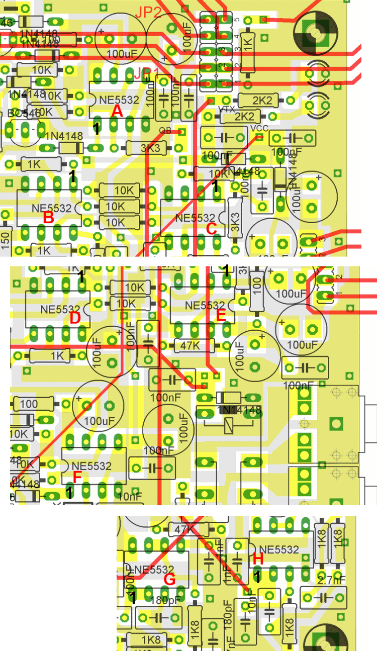
Upper Right Test Points
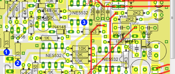
Middle Area Testpoints
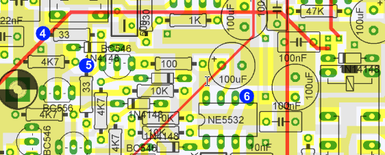
Lower Right Test Points
Test Measurements
| Testpoint | Units | Nominal Value | Author's | Yours |
|---|---|---|---|---|
| Point 1 | Vdc | 6.1 | _______ | |
| Point 2 | Vdc | 6.1 | _______ | |
| Point 3 | Vdc | 6.1 | _______ | |
| Point 4 | Vdc | 6.1 | _______ | |
| Point 5 | Vdc | 6.1 | _______ | |
| Point 6 | Vdc | 6.1 | _______ | |
| Point 7 | Vdc | 6.1 | _______ | |
| Point 8 | Vdc | 6.1 | _______ | |
| Point 9 | Vdc | 6.1 | _______ |
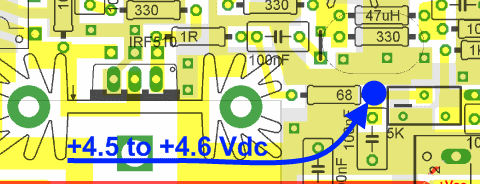
PA Bias Test
Test Setup
- Power ON
- Power up the SDR Software (e.g., GSDR) and put the rig into TX mode (e.g., using the "TUN" button)
- Test the voltage (with respect to ground) at the testpoint.
- You should see between 4.5 and 4.6 V dc
- If you do not see voltage in this range, adjust the 5k trimmer pot (shown to the right of the test point until the voltage is in range.
- Return the rig to RX mode/remove power from the rig
Final RX Test
Test Setup
Connect the SDR transceiver to a good resonant antenna or a 50 Ohm dummy load.
Initial adjustment: you would need a separate ‘control’ receiver tuned on the 20m band.
- Disconnect the soundcard input [TX I/Q “From sound card jack”]
- Disconnect the G3020 from the power supply
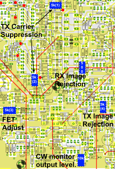
- A Reference the graphic below to locate the various trimmers used in the adjustment processes:
- Before activating the G3020 TX, adjust the TX carrier suppression 5K trimmers for minimum signal strength (typical voltage at trimmer is +2.5V +/- 0.1-02V) Both of these Y502 pots must match for Transmit I and Q carrier null to work properly. They should be set to exactly 2.50 volts wiper-to-ground (wiper is designated in the graphic as a red dot). These two Y502 pots then will null your carrier within a few hundreths of a volt from each other and very close to 2.50 volts.
- Disconnect the G3020 from the power supply
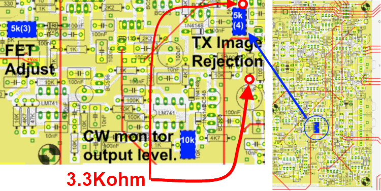
- Measure the resistance on the two testpoints in the graphic below and adjust the TX Image Adjust trimmer until the resistance is 3.3K ohms
- Connect your G3020 Antenna to a 50 ohm Dummy load (or antenna properly resonated for 20m (14.242 MHz, to be precise).
- Power up the G3020 and load/run your SDR Software (the steps below assume you are using GSDR)
- These steps assume you have your G3020's center frequency at 14.232 MHz.
- Tune your G3020 to transmit on a frequency 10 kHZ ABOVE the center frequency (14.242 MHz)
- Turn on your control receiver and tune it to the image frequency (10 kHz BELOW the center frequency, or 14.222 MHz.
- Connect the sound card TX I/Q output to the "From PC Soundcard" jack
- Set the GSDR (or other software) to "TUNE" so your G3020 is transmitting into the dummy load or antenna at the set frequency
- Adjust the image seen on the control receiver to obtain the max image rejection (using the TX Image Rejection 5K trimmer).
If your control receiver has a S meter, you should be able to track your adjustment as the S meter reflection of the image drops, ideally from 5 S units, e.g. from S6 to S1
If you see no evidence of the image signal (or the main signal) on the control receiver, check the G3020's final transistor. It shoujld get hot even in tune mode.
[Please note: refer to G40 homepage for more information in regard to adjustment procedure and Connection to Sound card and PC.]
To test the completed G40 Transceiver, the builder is directed to the extensively documented RX/TX Test Procedure on the GenesisRadio website.