LP Filters and Pre-Amp Introduction
General
This stage adds in the low pass filter bank and the infrastructure for switching in or out the 18 dB attenuator and/or the 15 dB RF preamplifier.
The two switches control the VRX to the two relays K2 and K3. K2 switches the attenuator pad (pi-network of one 220 ohm and two 68 ohm resistors) into or out of the RF chain; K3 switches the 2N3866 pre amplifier into or out of the RF chain.
(go directly to build notes)LP Filters and Pre-Amp Schematic
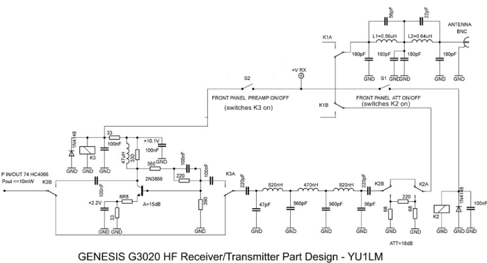
(go directly to build notes)
LP Filters and Pre-Amp Bill of Materials
Stage Bill of Materials
(resistor images and color codes courtesy of WIlfried, DL5SWB's R-Color Code program)
| Check | Count | Component | Marking | Category |
|---|---|---|---|---|
| ❏ | 1 | 1K5 (1.5k) 1/4W 1% | brn-grn-blk-brn-brn
 | 1/4W |
| ❏ | 2 | 220 1/4W 1% | red-red-blk-blk-brn
 | 1/4W |
| ❏ | 2 | 33 1/4W 1% | ora-ora-blk-gld-brn
 | 1/4W |
| ❏ | 1 | 330 1/4W 1% | ora-ora-blk-blk-brn
 | 1/4W |
| ❏ | 1 | 390 1/4W 1% | ora-whi-blk-blk-brn
 | 1/4W |
| ❏ | 1 | 560 1/4W 1% | grn-blu-blk-blk-brn
 | 1/4W |
| ❏ | 2 | 68.0 1/4W 1% | blu-gry-blk-gld-brn
 | 1/4W |
| ❏ | 1 | 6R8 1/4W 1% (6.8) | blu-gry-blk-silver-brn
 | 1/4W |
| ❏ | 3 | JRC27F/012 relay | JRC27F/012
 | 12V relay |
| ❏ | 3 | 1N4148 | 1N4148
 | Axial |
| ❏ | 9 | 100 nF | 104
 | Ceramic |
| ❏ | 2 | 220 pF 5% | 221
 | Ceramic |
| ❏ | 2 | 56 pF 5% | 56J | Ceramic |
| ❏ | 2 | 560 pF | 561 | Ceramic |
| ❏ | 1 | 47 uH molded inductor 10% | yel-vio-blk-slv
 | Choke |
| ❏ | 1 | 470 nH molded inductor (0.47 uH) | yel-vio-slv_gld
 | Choke |
| ❏ | 2 | 820 nH molder inductor | gray-red-slvr-gld
 | Choke |
| ❏ | 2 | shunt wire (cut-off lead) | Cutoff | |
| ❏ | 4 | 180 pF disc ceramic | 181
 | Disc |
| ❏ | 1 | 22 pF disc ceramic | 22J
 | Disc |
| ❏ | 1 | 47 pF disc ceramic | 47J
 | Disc |
| ❏ | 1 | misc hookup wire | Hookup | |
| ❏ | 1 | TO-39 heatsink |
 | Misc |
| ❏ | 1 | 2N3866 NPN Transistor |
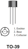 | TO-39 |
| ❏ | 2 | T50-6 | yellow
 | Toroid |
LP Filters and Pre-Amp Summary Build Notes
- Remove the temporary Wire
- Install 2N3866 and heat sink
- Wind and install L1 and L2
- Install Diodes, Resistors, and Chokes
- Install Capacitors
- Install Relays and Jumpers
- Install Wires
- Test the Stage
LP Filters and Pre-Amp Detailed Build Notes
Top of the Board
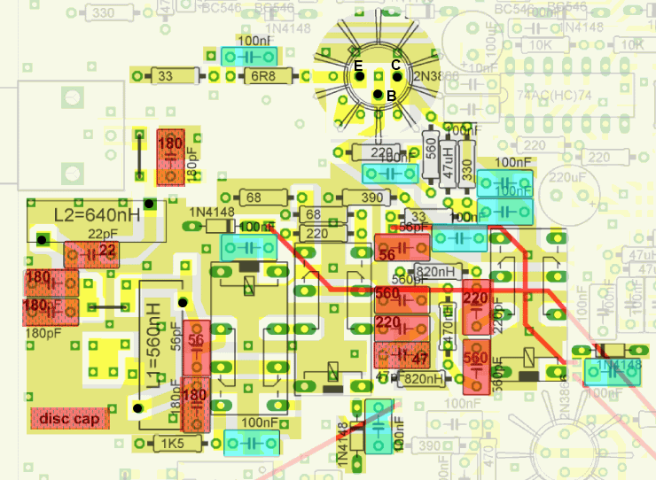
Remove the temporary Wire
Remove the wire that was used in the preceding phase to temporarily bridge the antenna signal into the mixers.
Install 2N3866 and heat sink
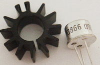
|
NOTE: the heat sink is factory supplied so tight that it would not be possible to place it over the 2N3866 after the transistor is soldered to the PCB. Therefore it is important to insert the 2N3866 into the heat sink first. |
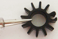
|
Prepare the heat sink by gently spreading its collar. |
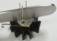
|
Place the transistor over the heat sink with the marking lip in the middle of the gap, push it down with the flat side of metal tweezers. The grip should be firm and tight (if it is too tight or loose, remove the transistor and adjust the collar) |
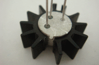
|
The transistor and its heatsink will resemble this when ready for mounting |
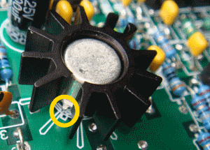
|
Place the 2N3866 into PCB (marking lip alignment as per photo). Solder it approx 4-5 mm (about 3/16") above PCB, just enough to clear any surrounding components. It is important to solder this transistor sufficiently raised so that its metal case does not touch any of the plated through holes (won't work correctly if it does so touch). TIP: Initially, solder one lead only. Then adjust for height and level, as needed, and then solder the other two leads. |
| Check | Designation | Component | Marking | Category | Orientation | Notes |
|---|---|---|---|---|---|---|
| ❏ | misc6-1 | TO-39 heatsink |
 | Misc | ||
| ❏ | Q6-1 | 2N3866 NPN Transistor |
 | TO-39 |
Wind and install L1 and L2
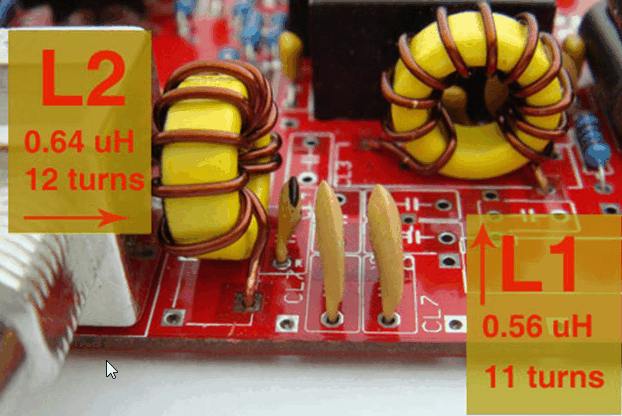
This transceiver requires exactly two wound toroids! L1 and L2, each wound on a T50-6 core with 0.8 mm (#20 AWG) wire, exactly as per photo.
Make sure to remove enamel coating and tin the leads before mounting. The length of wire required for each coil is about 13-14" (about 35 cm).
- L1: 11 turns - 0.56 uH (approximately 10" of #20 wire)
- L2: 12 turns - 0.64uH (approximately 11" of #20 wire)
Rule: Each pass through the center of the core (including the very first pass) counts as 1 turn. See the wb5rvz coil winding hints and tips for guidance on winding coils.
Install Diodes, Resistors, and Chokes
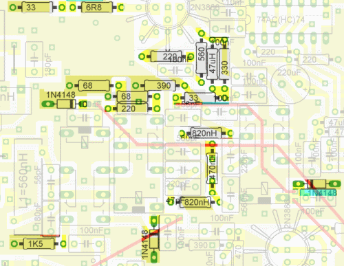
| Check | Designation | Component | Marking | Category | Orientation | Notes |
|---|---|---|---|---|---|---|
| ❏ | D6-1 | 1N4148 | 1N4148
 | Axial | ||
| ❏ | D6-2 | 1N4148 | 1N4148
 | Axial | ||
| ❏ | D6-3 | 1N4148 | 1N4148
 | Axial | ||
| ❏ | L6-1 | 470 nH molded inductor (0.47 uH) | yel-vio-slv_gld
 | Choke | ||
| ❏ | L6-2 | 820 nH molder inductor | gray-red-slvr-gld
 | Choke | ||
| ❏ | L6-3 | 820 nH molder inductor | gray-red-slvr-gld
 | Choke | ||
| ❏ | L6-5 | 47 uH molded inductor 10% | yel-vio-blk-slv
 | Choke | (reloc) | |
| ❏ | R6-1 | 6R8 1/4W 1% (6.8) | blu-gry-blk-silver-brn
 | 1/4W | ||
| ❏ | R6-2 | 33 1/4W 1% | ora-ora-blk-gld-brn
 | 1/4W | ||
| ❏ | R6-3 | 33 1/4W 1% | ora-ora-blk-gld-brn
 | 1/4W | ||
| ❏ | R6-4 | 68.0 1/4W 1% | blu-gry-blk-gld-brn
 | 1/4W | ||
| ❏ | R6-5 | 68.0 1/4W 1% | blu-gry-blk-gld-brn
 | 1/4W | ||
| ❏ | R6-6 | 220 1/4W 1% | red-red-blk-blk-brn
 | 1/4W | ||
| ❏ | R6-7 | 220 1/4W 1% | red-red-blk-blk-brn
 | 1/4W | ||
| ❏ | R6-8 | 330 1/4W 1% | ora-ora-blk-blk-brn
 | 1/4W | ||
| ❏ | R6-9 | 390 1/4W 1% | ora-whi-blk-blk-brn
 | 1/4W | ||
| ❏ | R6-10 | 560 1/4W 1% | grn-blu-blk-blk-brn
 | 1/4W | ||
| ❏ | R6-11 | 1K5 (1.5k) 1/4W 1% | brn-grn-blk-brn-brn
 | 1/4W |
Install Capacitors
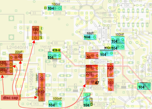
| Check | Designation | Component | Marking | Category | Orientation | Notes |
|---|---|---|---|---|---|---|
| ❏ | C6-16 | 22 pF disc ceramic | 22J
 | Disc | ||
| ❏ | C6-17 | 47 pF disc ceramic | 47J
 | Disc | ||
| ❏ | C6-1 | 56 pF 5% | 56J | Ceramic | ||
| ❏ | C6-2 | 56 pF 5% | 56J | Ceramic | ||
| ❏ | C6-18 | 180 pF disc ceramic | 181
 | Disc | ||
| ❏ | C6-19 | 180 pF disc ceramic | 181
 | Disc | ||
| ❏ | C6-20 | 180 pF disc ceramic | 181
 | Disc | ||
| ❏ | C6-21 | 180 pF disc ceramic | 181
 | Disc | ||
| ❏ | C6-3 | 220 pF 5% | 221
 | Ceramic | ||
| ❏ | C6-4 | 220 pF 5% | 221
 | Ceramic | ||
| ❏ | C6-5 | 560 pF | 561 | Ceramic | ||
| ❏ | C6-6 | 560 pF | 561 | Ceramic | ||
| ❏ | C6-10 | 100 nF | 104
 | Ceramic | ||
| ❏ | C6-11 | 100 nF | 104
 | Ceramic | ||
| ❏ | C6-12 | 100 nF | 104
 | Ceramic | ||
| ❏ | C6-13 | 100 nF | 104
 | Ceramic | ||
| ❏ | C6-14 | 100 nF | 104
 | Ceramic | ||
| ❏ | C6-15 | 100 nF | 104
 | Ceramic | ||
| ❏ | C6-7 | 100 nF | 104
 | Ceramic | ||
| ❏ | C6-8 | 100 nF | 104
 | Ceramic | ||
| ❏ | C6-9 | 100 nF | 104
 | Ceramic |
Install Relays and Jumpers
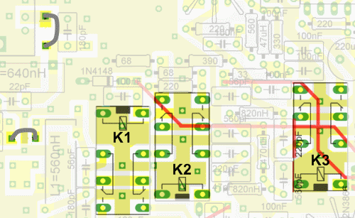
| Check | Designation | Component | Marking | Category | Orientation | Notes |
|---|---|---|---|---|---|---|
| ❏ | misc6-1 | shunt wire (cut-off lead) | Cutoff | |||
| ❏ | misc6-2 | shunt wire (cut-off lead) | Cutoff | |||
| ❏ | K1 | JRC27F/012 relay | JRC27F/012
 | 12V relay | ||
| ❏ | K2 | JRC27F/012 relay | JRC27F/012
 | 12V relay | ||
| ❏ | K3 | JRC27F/012 relay | JRC27F/012
 | 12V relay |
Install Wires
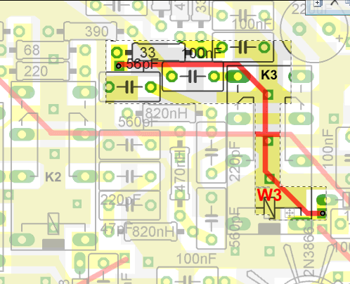
Install the (permanent) W3 wire. Preferrably on the underside of the board, this wire connects the control of relay K2 to the mount point for the Attenuator Switch, allowing the Attenuator switch to switch VRX in or out of the relay.
You can insert left-over component lead snippings or other wire snippets into the holes at either end of the wire (as markers, from the topside), then turn the board over and connect the permanent wire to each hole through which you inserted the "markers".
| Check | Designation | Component | Marking | Category | Orientation | Notes |
|---|---|---|---|---|---|---|
| ❏ | W3 | misc hookup wire | Hookup |
LP Filters and Pre-Amp Testing
Coil Continuity
Test Setup
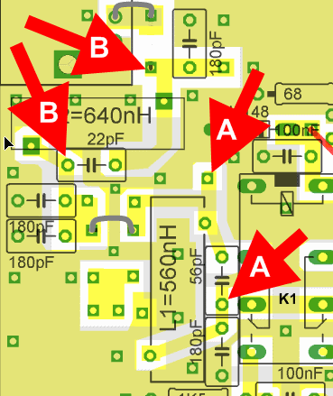
Test the continuity of the coils' windings by probing the matching (A-to-A, B-to-B) test points with your ohmmeter.
Test Measurements
| Testpoint | Units | Nominal Value | Author's | Yours |
|---|---|---|---|---|
| L1: A-to-A | ohms | 0 | tbd | _______ |
| L2: B-to-B | ohms | 0 | tbd | _______ |
Voltage Test
Test Setup
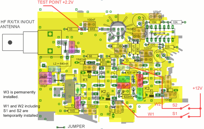
Tack-solder wires W1 and W2 (including S1 and S2) temporarily for purposes of this test.
Refer to Final Board Layout Diagram for final wiring configuration.
Test for 2.2 Vdc with S2 (Pre-Amp) on and then Off
S1(Attenuator) Should turn on relay K2
Test Measurements
| Testpoint | Units | Nominal Value | Author's | Yours |
|---|---|---|---|---|
| Junction of 33 and 6.8 ohm resistors: S2 ON | Vdc | 2.2 | tbd | _______ |
| Junction of 33 and 6.8 ohm resistors: S2 OFF | Vdc | 0 | tbd | _______ |
Attenuator Test
Test Setup
AttenuatorTo test attenuator preamplifier:
- Turn S1 (attenuator) switch OFF
- Turn S2 (pre-amp) switch OFF
- Power on the board and connect I/Q out to PC's stereo Line-In (or "mic") jack
- Tune the SDR PC program to a 40m signal (or connect a signal generator)
- Observe signal strength
- Turn S1 (attenuator) switch ON
- Turn S2 (pre-amp) switch OFF
- Observe signal strength - signal will decrease for approximately 17dB
Pre-Amp Test
Test Setup
With power still on and signal present: in SDR Software
- Turn S1 (attenuator) switch OFF
- Turn S2 (pre-amp) switch OFF
- Observe signal strength
- Turn S2 (pre-amp) switch ON
- Observe signal strength - you should see an improvement of 15dB